
Cactus V6 Review
Measurements
I performed the following qualitative and quantative tests:
Reliability and Reach
 |
| Impressive Reach The quoted "100m" reach seem to be a conservative figure. |
The maximum distance between transmitter and receivers is specified to be 100m but in a test the V6 still fired another V6 and an RF60 from 140m away. Battery levels were shown as low by the indicator during my test and evening cold had set in already, so the figure does not represent a "best case" scenario.
The image to the right is from a V5 test I performed quite a while ago. The V6 and V5 share the same 2.4GHz platform which is why they are compatible with each other (see next section).
Reliability is rock solid. Neither my V5 nor the V6 alpha units ever misfired.
Proximity Tolerance
Starting with firmware version V1.0.152, the V6 supports an optional "short range" mode. The default mode is "long range" and while it supports the 100m+ reach, its strong signal also means that a receiver can experience signal overload if a transmitter comes too close.
The respective minimum distance depends on the exact juxtaposition of transmitter and receiver and also on how they are rotated against each other. In the worst case, one will have to keep them about 20cm (~8in) apart to avoid signal overload.
The "short range" mode reduces this minimal distance to zero. I could not provoke any misfires, no matter how hard I tried. This is very welcome for situations in which the transmitter may come very close to the receiver, e.g., for table top product photography, macro photography, etc.
In an outdoor test, I still obtained ~30m reach using the "short range" mode. This means that it should be safe to leave the V6 in "short range" mode and only switch to "long range" mode for special shoots involving long distances or walls that separate transmitter and receiver.
Banding
The V6 support sync speeds of up to 1/1000s so the 1/180s sync speed of a Pentax DSLRs are not a challenge at all. Slow triggers can introduce dark bands at the bottom of frames at the highest sync speed, but the V6 does not suffer from this problem.
Flash Profiling Accuracy
 |
| Flash Profile Accuracy Target levels are produced with very good to excellent accuracy. |
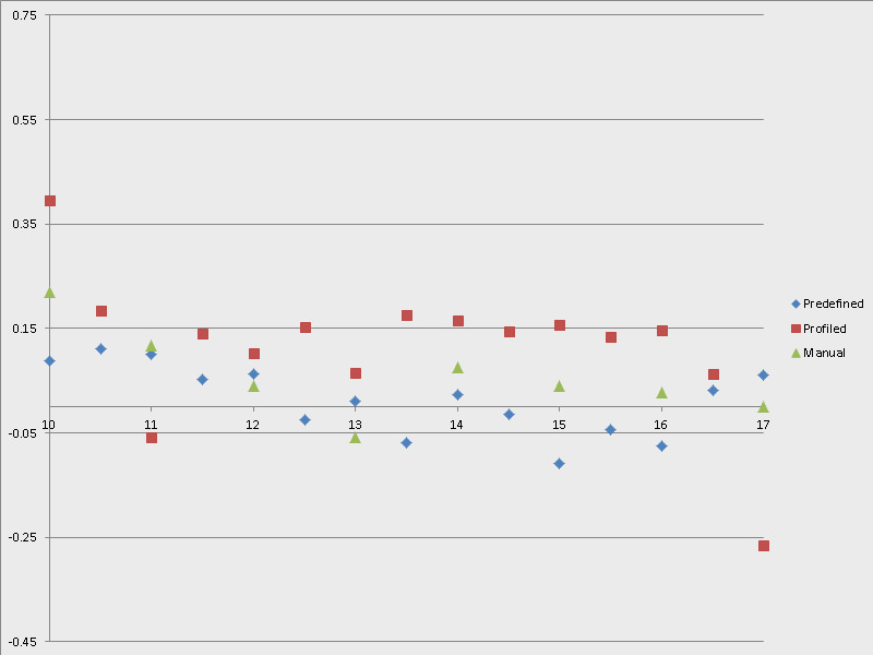
The accuracy of both pre-defined and custom created flash profiles is very good to excellent. See the diagram to the right regarding the errors (deviations from target output levels in EV) for a Canon 540EZ (click on the diagram to see a larger version).
I have measured light output from 1/1 down to 1/128 in half stop steps, mapping 1/1 to “EV 17” and 1/128 to “EV 10” accordingly.
The green dots show the errors of the Canon 540EZ in manual mode (i.e., without involving a V6). Note that even the flash itself shows errors of 0.1EV and 0.22EV at the lowest levels. The other levels are impressively precise, though. N.B., there are only half as many green dots, as the Canon 540EZ natively only supports full stop changes.
The blue dots show the errors of the predefined 540EZ flash profile. As you can see, the minute deviations are very similar to those of the native manual levels. The predefined profile is even more accurate at the lowest levels! This is pretty spectacular performance.
The red dots show the errors of a custom flash profile that I created for the 540EZ using the “learning” feature of the V6. As you can see errors stay below 0.2 EV most of the time. The “1/1” level is down by 0.26 EV because I applied an overall compensation of “-0.3EV” in order to bring the rest of the levels down a bit. I will repeat the creation of the flash profile using the same zoom setting as I used for measuring just to make sure that the zoom setting does not make a difference (it should not).
While the custom profile shows the highest deviations, note that we are talking about about absolute deviations of “1/3” stop or less only. In practical circumstance, this equates to pretty much “nothing”, as such small deviations are easily overshadowed by changing the subject to light distance a little bit. Also, note how smooth the implied red curve is which means that small relative adjustments made to the flash power will actually have the desired effect (instead of negating the adjustment because the relative error is so high). For perspective, let us assume we want to increase the flash power from 1/8 to 1/8 +0.5. For this adjustment to not have the intended effect (here of increasing the level slightly), there would have to be a gap (with a negative sign) between the error values for 1/8 and 1/8 +0.5 of 0.5 EV or more. Even the worst gaps stay well below such thresholds.
Absolute Power Mode Accuracy
 |
| Absolute Control Three flashes with different guide numbers harnessed to provide the same output. |
The absolute power mode equalises differences in maximum guide numbers very well. I tested this feature using a GN 54, GN 56, and GN 58 flash at the same absolute levels. See the images to the right for the results which are very close to each other in terms of exposure.
One would not notice very large differences between flashes with such close maximum guide numbers anyway, however, I did not have a weaker flash available for testing.
In any event, one can always use a temporary group offset or permanent flash profile offsets to counteract any deviations.
Lo-Power Level
I measured the “Lo power” level as reducing the output to ~2/3 of a stop below 1/128 power. This is 1/3 of as stop shy of a true 1/256 level, as it is natively supported by the Metz 58 AF-2, for instance.
Presumably, a compromise had to be made between minimising the flash duration and ensuring that the flash fires at all. A certain minimum voltage is needed to ignite the flash tube and, after all, flash models that only provided 1/128 as their lowest level natively are operated outside their specification with this “Lo power” level.

