
Astrophotography Part 3 of 6: Making a Barn Door Tracker
Do-it-yourself tracking mechanism
By K David in Articles and Tips on Dec 11, 2015
 Pier and Stars (171s exposure) - Click for larger size
Astronomical photography is one of the newest trends among photographers. High-quality digital cameras with good high-ISO performance combined with fast, high-quality optics from makers like Pentax, Samyang, and Sigma are taking astrophotography out of the enclaves of astronomers and putting it in the hands of hobbyists, too. This six-part series examines various elements of astrophotography.
Our third installment in the series looks at how to make a sidereal tracker (barn door tracker) at home. We'll go through types of trackers and discuss, in depth, the tracker I elected to build: a two-arm Type 4 model. This article provides drawings and a parts list to build one like mine. It also provides the algebra needed to make a larger or smaller unit to fit your camera, budget, and space.
 Two-arm, Type Four Barn Door Tracker
Why Build a Barn Door Tracker?
Before we begin discussing barn door tracker types and delve into construction, it's important to answer why we want to build a tracker at home. The least-expensive systems for sidereal tracking on the market are around $300, which is affordable but also outside of the price range of many hobbyists. A home-made barn door tracker will cost less than half as much if you buy everything new and even less if you only buy the parts unique to the tracker (the motor, mount, tripod bushings, and tripod ball head). Hinges, scrap wood, and even lantern batteries can often be found lying around in a suitably stocked garage.
In addition to being an economical solution, building the tracker at home makes for some interesting stories, gives you a nice conversation piece, and can help you learn a lot about the way that stars and our planet interact. If you have a son or sons in Boy Scouts, this would also be a fantastic merit badge project.
The home-made barn door tracker replaces sidereal tracking systems such as the Vixen Polarie and iOptron Skytracker. The end result will be photos of stars, constellations, and galaxies that exist without trails and blurriness. Additionally, because these units can be more robust than commercial units, they allow the use of longer lenses than either the Vixen or iOptron models. The tracker will of course also exceed the capabilities of the Pentax astrotracer feature.
Barn Door Trackers: An Overview
Barn door trackers are a type of sidereal camera mount. Specifically, they are home-made devices that move your camera in alignment with the stars. These function in the same basic way as an iOptron Skytracker or Vixen Polarie. This means that both long-duration and time lapse exposures are the risk of seeing star trails is reduced. Thus, there is potential for much greater detail in your starscapes.
Barn door trackers differ from the two commercial units named above in that you need to build them yourself. Barn door trackers can be nearly free if you use reclaimed wood. If you buy all your parts new, as I did to establish pricing, the raw materials will cost between $80 and $125, depending on how you elect to construct your tracker. My materials were $125 because I built it to be excessively robust.
Construction time for mine, which is fairly complex, was about an hour and required a drill, various bits, and a chop saw. Obtaining wood or plexiglass pre-cut to size will reduce construction time. There's a complete parts list at the end of this article that can be copied and used along with the engineering drawings provided. Parts that are harder to source than the local hardware store include links.
The most important question, though, is how accurate a home-made sidereal tracker can be. Here is my test shot, taken in a city setting, at 71.62 seconds using a 50mm lens.
 Seventy-two-second Test Shot (polaris marked)
The test image shows a great deal of promise given that the exposure exceeded one minute with a 50mm lens. Also, part of the sliding mechanism (designed to give the arms smoother movement) was lost during transport before this shot so the two arms were moving on a naked screw. For easy reference the north star (Polaris) has been marked.
As you can see, even at 72 seconds, the stars are fine, blur-free points. Some slight lens distortion in the upper left corner has caused blurring, but otherwise the results are very good. The results your barn door tracker provides, however, will vary based on the accuracy of your materials fabrication, hinge placement, and (if you elect to build a two-arm tracker) drive-camera contact point placement. Also, if you use a motor, that motor's accuracy will be imperative as will the motor's ability to move the camera's weight. Specific materials will be discussed later in the materials section.
Tracker Categories
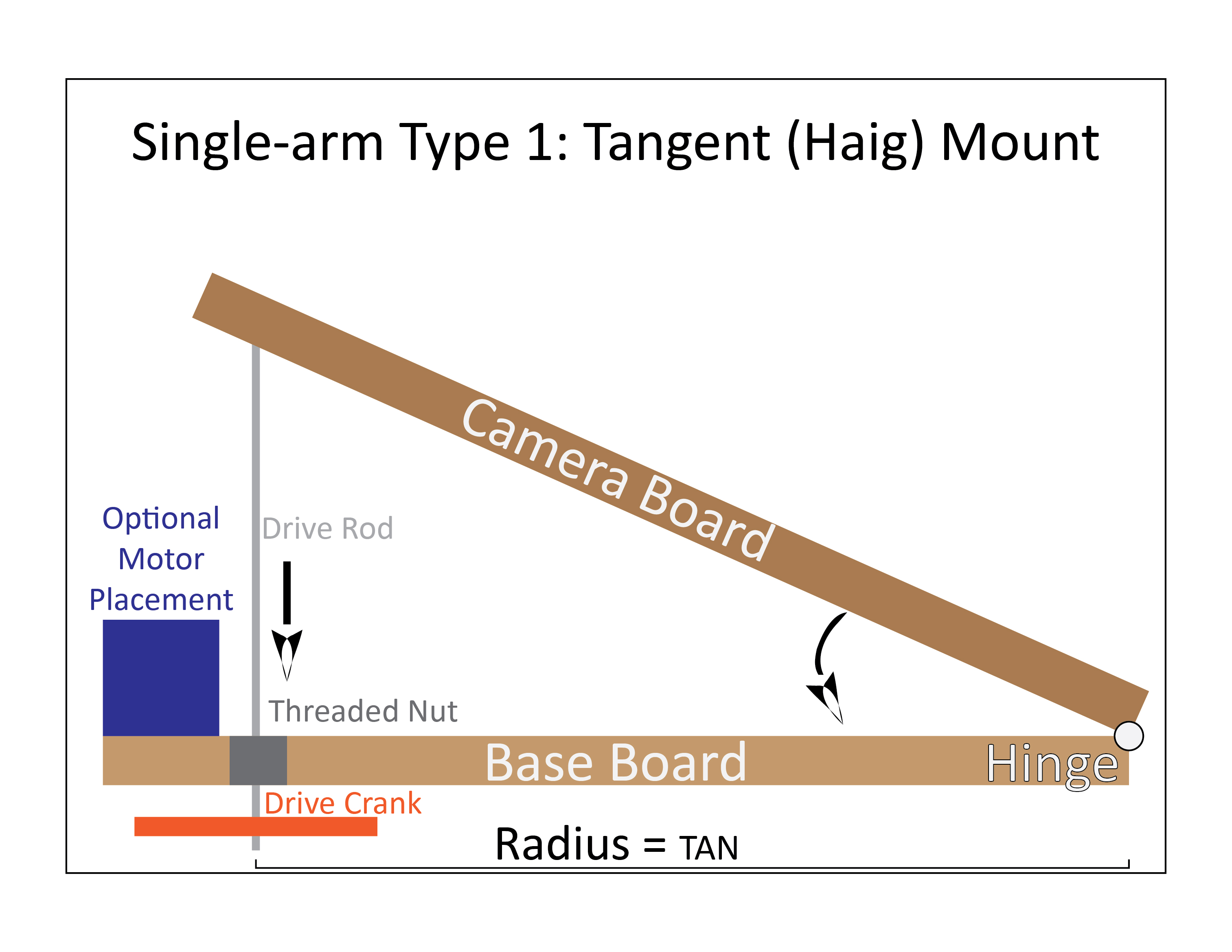
Two basic types of barn door trackers exist: single-arm and double-arm. A single arm tracker is just a hinge with two pieces of wood. One piece of wood attaches to a tripod and the other to your camera. Movement is done with a drive rod connected to either a motor or a hand crank. Double-arm trackers work similarly but in a more complex manner. Instead of the drive rod directly moving the arm with the camera, it connects to a second arm that the camera's arm then pivots from. This removes tangent errors that are intrinsic to single-arm models.
Single-arm Barn Door Trackers
 Simple Single-arm Barn DoorTracker
Single-arm trackers, as hinted at in the previous paragraph, suffer from tangent errors. That means that when the camera arm moves it does not move in a perfect circle that counters the earth's rotation. This is caused by the design, angles of rotation, and movement.
To put this in mathematical terms, after 20 minutes a single-arm barn door tracker can be reasonably expected to have input 20 arc-seconds of error into a camera's movement. By 50 minutes, that figure can reasonably be expected to reach 100 arc-seconds. How noticeable that is depends on how wide your lens is, with wider lenses being less susceptible to errors. However, even a fisheye lens will see tangent errors after about five or six minutes with a single-arm model.
Straight-rod
Straight-rod barn door trackers are, without equal, the easiest type of astrotracking unit to make. A sturdy hinge, two wood planks, a 1/4-20 threaded rod, a nut in the base board, a drive crank that could just be a vice grip, and a tripod mount are all that a photographer needs to build a tracking unit that can provide an image with reasonable tracking capabilities for up to two minutes with a wide-angle lens. Though simple, these don't deliver the best images and are highly susceptible to camera shake as the drive rod moves.
A straight-rod variant uses a low-friction curved plastic piece to mounted on the camera arm to compensate for tangent errors. These, insofar as I know, cannot be readily sourced and require custom fabrication.
Curved-rod
Curving the rod in a manner that mirrors the earth's radius helps to offset the previous tracker's tangent errors. Curving the rod comes with inherent risks, such as nut binding. It also makes the movement more difficult as the rod can no longer be turned so the tracker requires that the nut be turned. For that reason, despite this unit being relatively easy to make, I elected to avoid a tracker of this design.
Double-arm Barn Door Trackers
This article contains a number of high-resolution images for the tracker design and the algebra used to scale it up or down. If you'd prefer to use PDF files in lieu of high-resolution images, follow this link.

Type 4 Double-arm Barn Door Tracker
Four types of two-arm barn door trackers exist. They have different levels of suitability with one (Type 2) being worse than the single-arm models.
Types 1 to 3
The type 1 to 3 models provide lower levels of efficacy in tracking than the Type 4. Because I elected to skip these models, I did not develop drawings of them. Suffice to say, they vary from each other and the Type 4 on drive arm placement and length.
Type 4
Compared to the Type 4 drawing above, my tracker swapped the drive and camera arm placement. The results work quite well. Swapping the arms works better than the design typically available and based on one of the two Type 4 variant drawings commonly found online. Swapping arm placement allows for more control over the critical item placements and allows for a battery pack or motor to be mounted on the unit, if desired.

In addition, the base board on my unit is articulating off another base board. This allows the base board to be readily articulated to the proper angle without adjusting tripods. The above photo shows how my baseboard articulates off of another board. The threaded rods (pre-taped to simplify angling in the field) position the base board to have an angle that matches the latitude. This allows the angling to be done without the use of tripods and creates an inherently more stable unit.
The articulating base is optional. The articulation can be done with the tripods, but that changes the tripods' center of gravity and could easily result in the assembly tipping over.
Type 4 Barn Door Tracker Algebra
The best part about this section is that if you want to skip it, you can. The next section has the drawings I developed for my Type 4 Barn Door Tracker build. The unit I built will work on any APS-C or full-frame DSLR or 35mm film camera without modification for size. Smaller cameras also work, but a smaller unit could also be built to move a smaller camera.
We'll go over the algebra for the Type 4 tracker so that you can scale up or down your tracker to meet your needs. If you use a Pentax 645 or 6X7 system, for instance, my as-designed system will be insufficient for your camera size. Likewise, if you use the Pentax Q system, you can make a significantly smaller unit. Click on the below image to view a larger version. Click on this link to download the 3,300 X 2,550 pixel image.
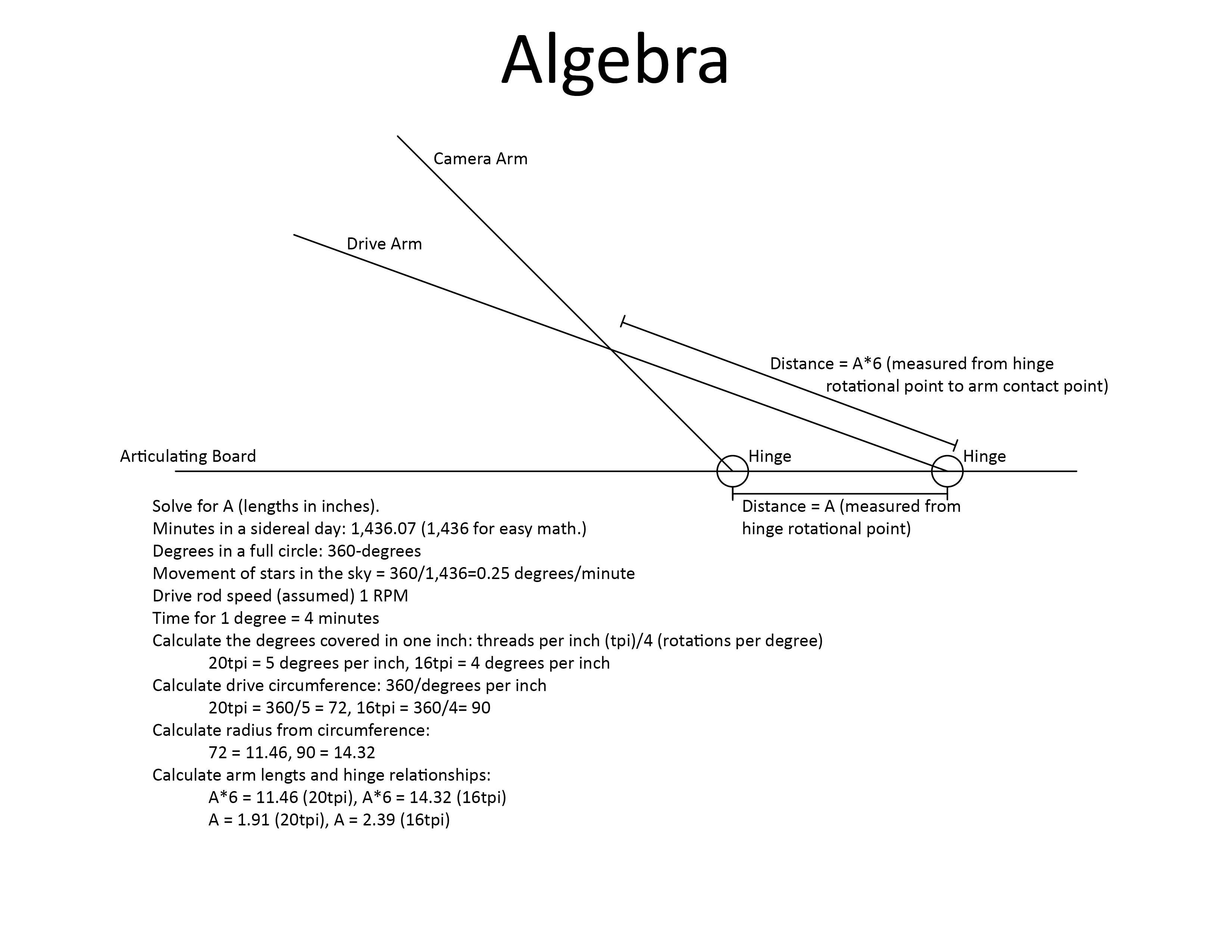 This is a line drawing of the tracker base board, drive arm, and camera arm. All of the calculations we need are determined while obtaining the distance between the rotational centers of the hinges connecting the drive and camera arms to the base board. Remember, the hinges are spaced based on their rotation center: the pivot point. Aligning items based on the hinge plate or outside edge can throw off component placement and introduce tangent error more quickly than the Type 4 design needs to.
To ascertain the size of your board and scale your unit to accommodate your camera, we need to solve for A: the distance between the two hinges' rotational axes. For easy reference, key points in this section are in bold.
A sidereal day has 1,436.07 minutes. That's the time required for a star in the sky to make a full 360-degree rotation. For our needs, using 1,436 is sufficient. A full circle has 360 degrees. These two givens form the basis of our tracker scaling math.
360 degrees/1,436 minutes=stars move in the sky at a rate of 0.25 degrees per minute.
Let's further assume that your drive rod will be moving at a rate of one rotation per minute (RPM). In my case, I used a high-torque one-RPM motor as my drive motor. With a stall weight of around 77 pounds, the motor can out-perform the tripod head and drive rod bind point.
At one RPM, stars move one degree every four rotations.
Likewise, if you have a ten RPM motor, you will cover one degree every 40 rotations. At 15 RPM, stars will cover one degree every 60 rotations.
Next you need to decide what type of threaded drive rod to use. For a Pentax Q or K-mount body, a 1/4-20 threaded rod will suffice. For a 645 or 6X7 body, a 3/8-16 rod may be a significantly better idea. The next step is to calculate the number of threads covered by one inch of drive rod length.
Movement=tpi/rotations per degree.
With a one RPM motor, a 20 teeth per inch (tpi) drive rod, the camera will track five degrees per threaded rod inch. With a 16 tpi drive rod, the camera will track four degrees per threaded rod inch.
The faster the motor you select, the longer your drive rod needs to be. Also, the larger your tracker needs to be. Using a motor faster than one RPM increases your materials sizes dramatically. A 1/2 RPM motor could be used to create a more compact unit; however, downscaling the unit size means construction needs to be more precise and there's less room for placing components such as the motor.
The next step is to calculate how long a circular drive rod would need to be to allow a 360-degree track. This is important as it lets us know how long our unit will be able to track as well as how long to make our drive rod to attain the desired tracking time.
360-degree Drive Rod Length=360/drive rod degrees per inch (5 for 1/4-20 and 4 for 3/8-16).
A 1/4-20 drive rod covers five degrees per inch. So using a 1/4-20 threaded rod means 360/5=a 72-inch circumference circle to cover a 24-hour tracking event. The lower your tpi number, the larger the drive rod will need to be. This tells us the length of drive rod needed for a theortical circular drive rod that could allow for a 24-hour tracking event.
Knowing the circumference (72 inches with a 1/4-20 drive rod, 90 inches with a 3/8-16) of the theoretical drive rod circle tells us the balance of the needed math. Using the circle's circumference, we can calculate the length needed for the camera arm. We need to know the radius of the theoretctical drive rod circle in order to calculate tracker size and component placement.
A 72-inch circle has an 11.46-inch radius.
Knowing the radius is 11.46 inches tells us that on the camera arm, the rotational center of the hinge needs to be 11.46 inches from the point where the camera arm rests on the drive arm.
To ascertain the relationship between hinge placement and camera arm hinge-to-contact distance, I used Dave Trott's design. Dave Trott has slightly different measurements than I do but the relationship is the same.
Taken as a given that the theoretical drive rod circle radius is A*6, we can determine A.
A*6=11.46. 11.46/6=1.91. The distance between the hinges' rotational centers needs to be 1.91 inches.
In solving that distance, we've also solved every other important piece of math for this build. The camera's drive arm, if you use a 1/4-20 drive rod, needs to connect 11.46 inches from the hinge's rotational center, meaning that it should be at least 12.5 inches long to accept the tripod ballhead mount as well as the wheel that will rest on the drive arm.
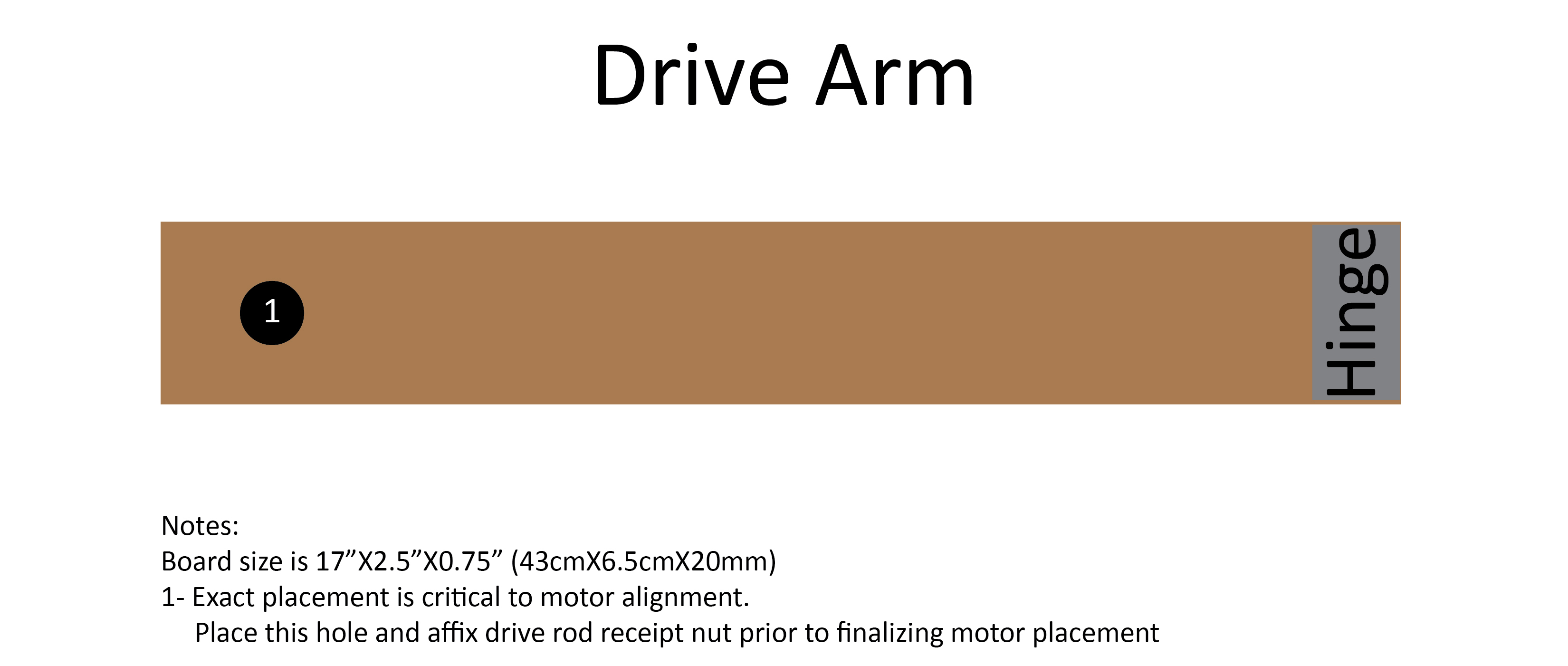
The drive arm needs to be longer than the camera arm, so I chose 17 inches (arbitrarily because it meant I didn't need to make another board cut.) The camera's base board should be neither longer nor shorter than the drive arm, so it needed to be 17 inches, too. If you make an articulating base board, it also needs to be 17 inches long.
Though the algebra drawing does not show it, the drive rod needs to connect A*7.2 from the rotational center of the drive arm's hinge. With a 1/4-20 drive rod, that's 13.75 inches.
Type 4 Barn Door Tracker Design Drawings
The following drawings are ones I developed to build my Type 4 Barn Door Tracker. Here is a link to all of the drawings in a single, 6,902 X 8,248-pixel image file. You can also click on each image to bring up a larger one. Links to each image are also provided at the end of their descriptive paragraph.
The base board is a stationary board. It rests flat. Adding a small bubble level to it would be a good idea. It also needs to have at least two tripod bushings on the underside. I used 1/4-20 to 3/8-16 reducer bushings for this. Stationary Base Board Image Download Link.
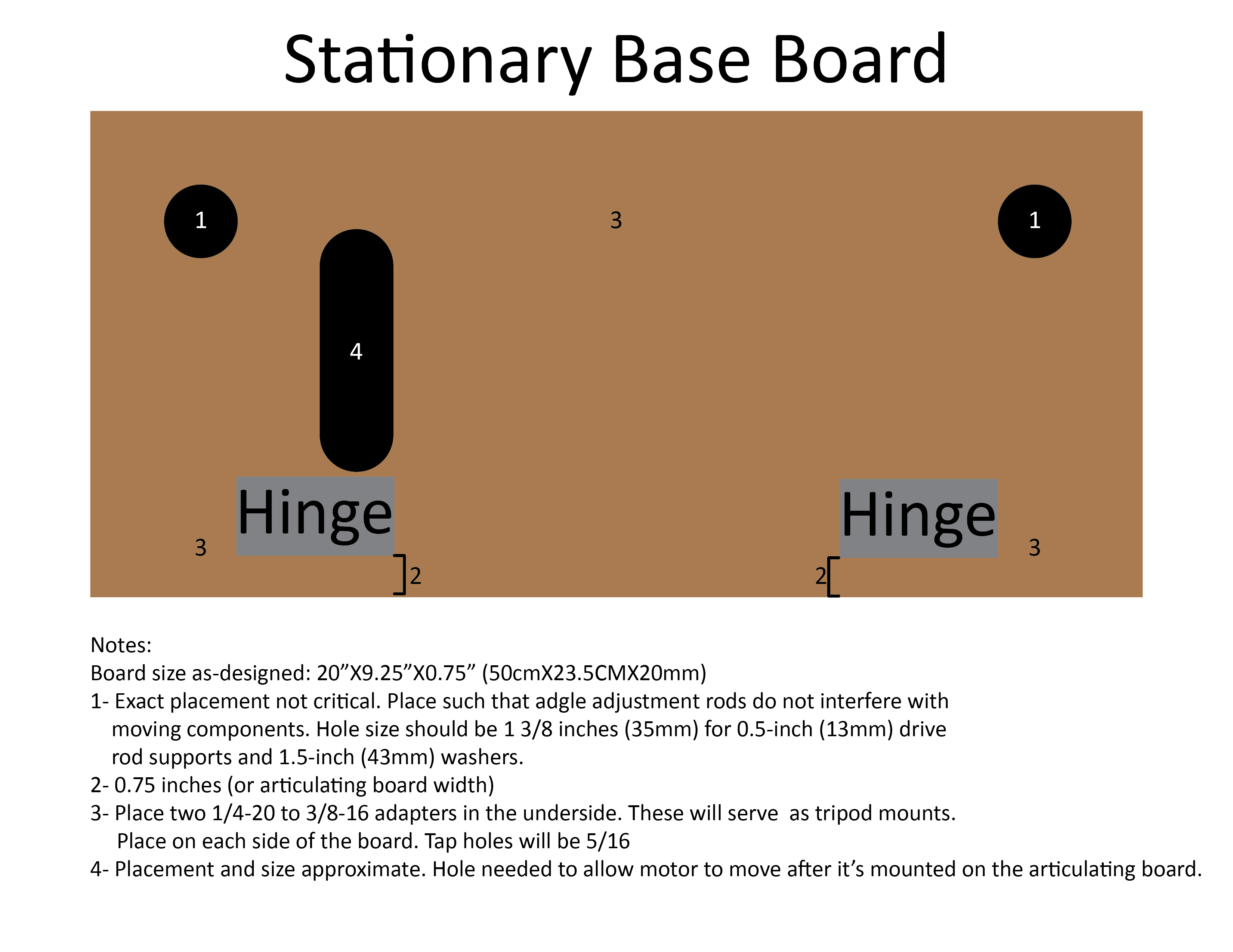 The stationary board has hinges, at least two, along what appears to be the bottom in this image. This allows the articulating base board to move upward and downward. The articulating base board needs to be angled to equal your latitude. For instance, in London, the angle between the stationary base board and articulating base board needs to be 51 degrees. Conversely, in Jakarta, it needs to be six degrees. Articulating Base Board Image Download Link
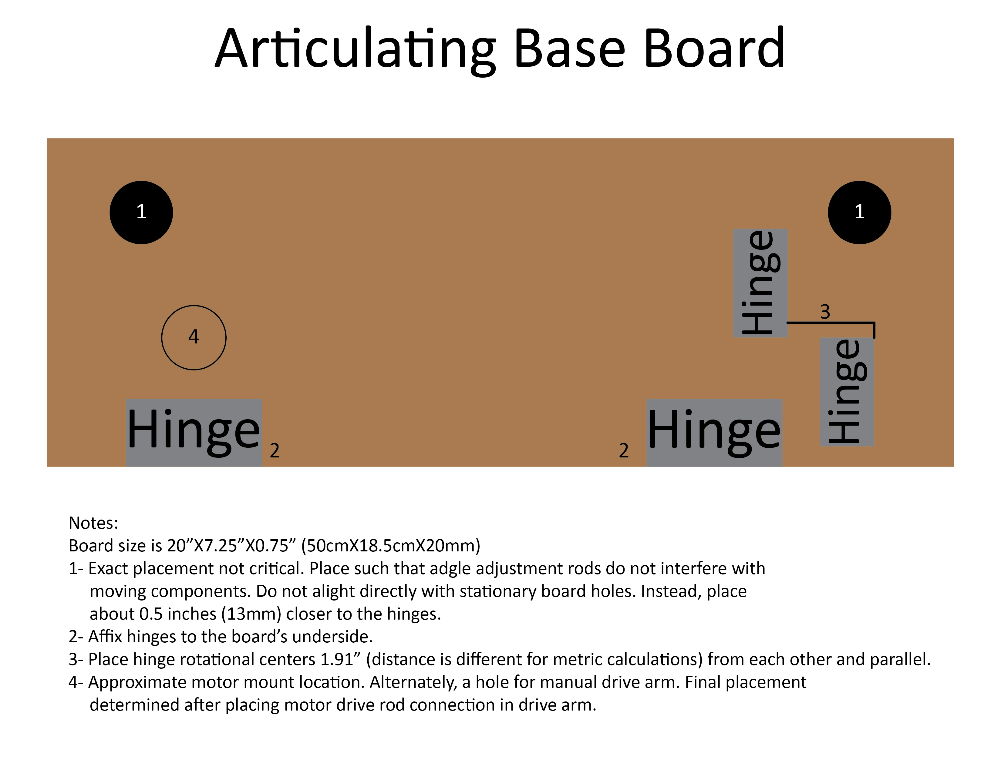 You'll note that there are two holes on this board that correspond to holes on the stationary board (but they are not placed directly in sequence. These holes need to be staggered as you'll be using large drive rods there to stabilize end of the board. This makes a stable triangle between the base board, articulating board, and large-diameter drive rods. Using drive rods, as pictured below, allows you to set up the angle indoors ahead of time, place tape over the threads to facilitate field set-up, and ensure that you aren't spending valuable dark time fiddling with adjusting parts and pieces and gauging angles with an angle finder.
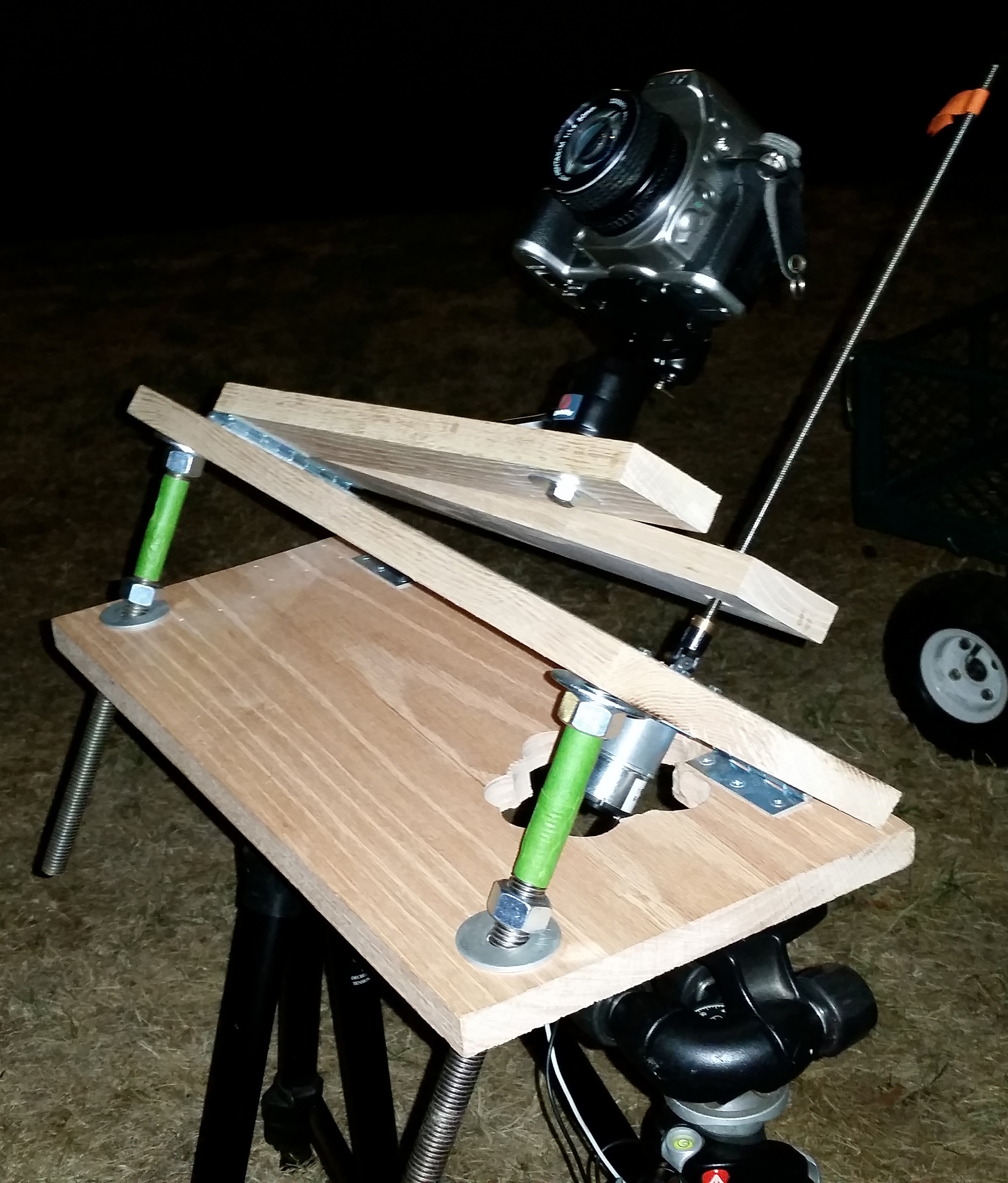
Note the use of drive rods, masked with green tape for easy field set up. The threaded rods keep the articulating board in place. I used 0.5-inch threaded rods here because they have to carry the weight of the entire assembly. You can also see how large, and incredibly ugly, my motor hole is. Oops.
The drive arm is a fairly simple item to construct. Drive Arm Image Download Link
 It's easiest to build the barn door tracker if the drive and camera arms are built ahead of time and then just attached to the articulating board. The last section in this article provides details on the construction process. Camera Arm Image Download Link

The last important piece is the motor connection. The motor cannot have just a straight drive rod coming out of the top or it will bind quickly. You can solve this by making an articulating motor mount, installing a threaded cross dowel in the drive arm, or making an articulating threaded rod connection in the drive arm. The fastest option, which adds about 20 more minutes of movement, is a single-joint universal joint in the assembly. I elected to install a universal joint and also use a long cross dowel drilled into the board width-wise to allow maximum articulation without binding. A drive rod binding event can destroy a motor.
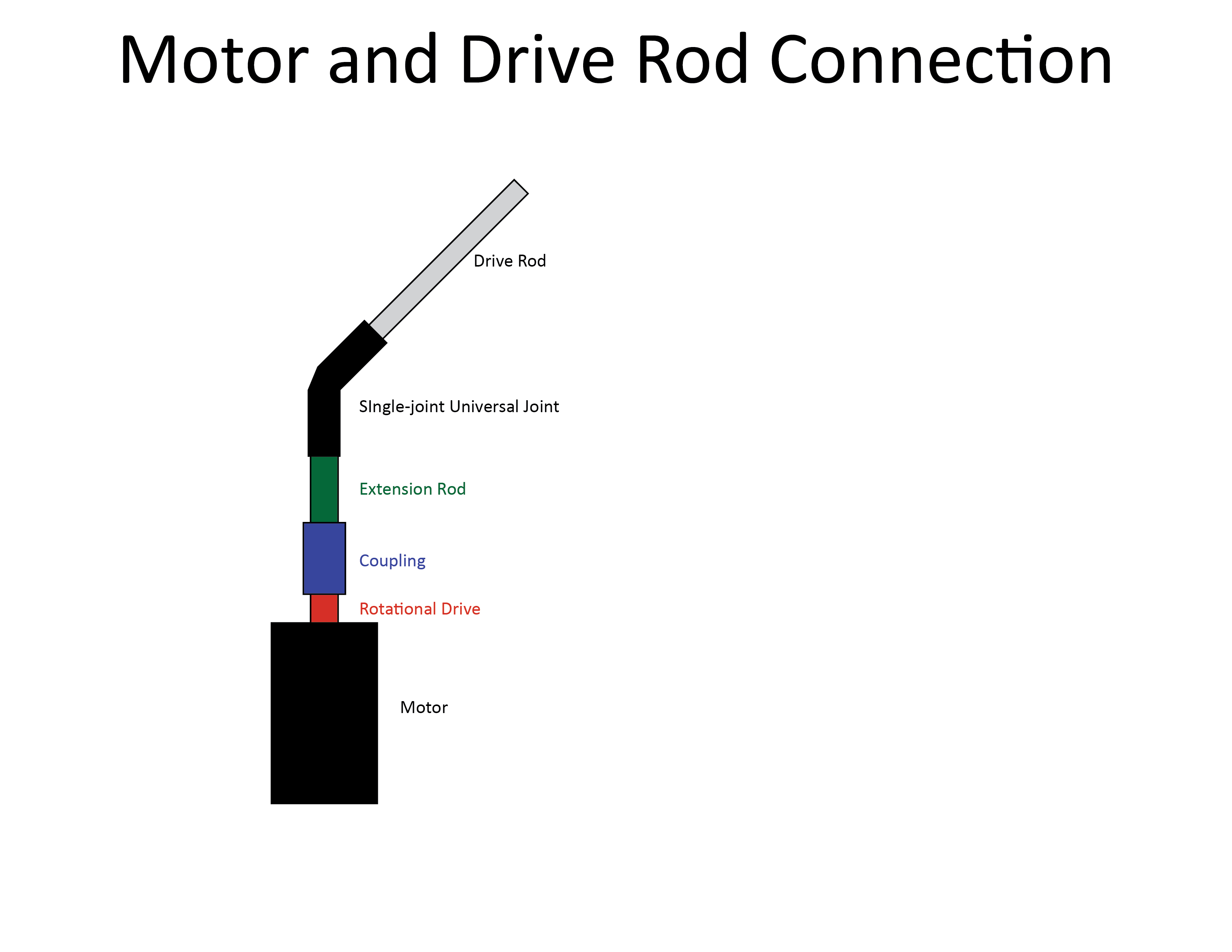 Using a coupling and extension rod, or part of the drive rod, you can insert a universal joint about an inch or two above the motor. This will increase the time before the drive rod and nut bind. This in conjunction with a cross dowel placed through your board can give you the maximum available tracking time. If you don't have a cross dowel, a simple nut will work. Whatever you affix the drive rod to the drive board with, it has to be fixed to the board to prevent it from introducing camera shake or slippage.
Type 4 Barn Door Tracker Parts List
Here are the parts I used for my build. In addition, you'll need various screws and the tools to construct the barn door tracker. For specialty items, the bullet includes a link to that item.
- 1X 17X2.5X0.75 wood or plexiglass board (board)
- 1X 14X2.5X0.75 board
- 1X 17X7.25X0.75 board
- 1X 17X9.25X0.75 board
- 4X hinges (These should be sturdy and piano hinges are not suggested.)
- 1X one RPM motor
- 1X motor mount
- 1X 1/4-20 drive rod
- 1X 1.25-inch 1/4 D-shaft
- 1X 6mm to 1/4-inch coupler
- 1X 1/4-inch to 1/4-inch coupler
- 1X 1/4-inch to 1/4-inch universal joint
- 1X 1/4-20 cross dowel or wide-flange, tapped-flange nut
- 1X 12-volt lantern battery
- 2X suitable lengths (at least four feet) of 12 AWG braided wire
- 4X solder-on or crimp-on 12 AWG alligator clips
- 4X lengths of 12 AWG-sized shrink wrap
- 1X tripod ball head with 3/8-16 nut and washers to affix it
- 1X 3/8-16 nut to retain tripod mount when head is removed
- 2X 1/4-20 to 3/8-16 adapters for tripod bushings
- 1X sliding door wheel and L-bracket, wheel and screw assembly, or an RC car wheel, etc.
- 2X (no fewer) 0.5-inch drive rods (at least 12 inches)
- 4X 0.5-inch nuts
- 4X 0.5-inch large-diameter washers
- 1X angle finder
- 1X 12-volt lantern battery
Type 4 Barn Door Tracker Construction Process
Construct the Boards
Begin by putting all the holes in the boards. Afterwards, affix the hinges to the camera and drive arms. Then affix the hinges to the articulating board. The articulating board is the easiest to mount. Place it, edge-on-edge, to the base board with the hinges resting on the base board. Then affix the hinges.
It's important to affix the articulating board to the base board first because attaching the articulating board accurately if the camera and drive arm are mounted already will be challenging. After the articulating board is mounted to the base board, close the assembly and attach the camera and drive arms. Be very certain of your placement with these components. They are not easy to move if they've been affixed incorrectly.
Construct the Motor Assembly
Begin by assembling all the parts of the motor assembly except the drive rod. For the time, leave that off. It will be easily bent during the rest of the construction process.
Install the motor and mounting bracket to the base board. Be sure that you don't over-screw the motor mount if you used the suggested materials. Over-screwing the bracket can impair the motor's ability to spin smoothly in the bracket and then introduces camera shake to your images.
Wiring
The wiring portion can be as simple or as complex as you'd like. I elected to keep it simple and avoided switches and fixed wiring. A dipole switch can be cross-wired and mounted to create a fixed switch. And, if there's curiosity on how to do that, I'll add a wiring diagram to the next post.
For the most basic wiring, use your lengths of 12 AWG braided wiring and alligator clips. Slide the shrink wrap around the wiring, strip the wiring ends, braid them, and solder (preferably) or crimp them into the alligator clips. After the solder cools (if you elected the soldering route), use a heat source to shrink the heat-shrink wrap around the junction. Do this on both ends of both wires. You can then use an alligator clip to connect each pole of your 12-volt battery to each pole of the motor.
Finishing Details
A note on the power source. I tried a significant number of power sources for the motor I selected. These included two PX28 (six-volt) batteries, eight AA batteries, one 9-volt and two AA batteries, and eight D-cell batteries. All of these delivered sufficient voltage to power the motor at one RPM. However, all of them were draining far outside of their safe operating range. The AA batteries drained so quickly that they melted the solder on one of their holder's retaining springs (after three minutes.) The D cells were so hot (after two minutes) that I burned my fingers (getting a blister) pulling one out of its holder (after disconnecting the batteries from the motor.) Do not use small-duty batteries like these.
I found two options sufficient to provide safe, burn-, explosion-, and fire-risk-free power for the 12-volt motor. The first is the 12-volt battery included on the parts list. The second was two six-volt lantern batteries connected in series with 12 AWG braided copper wire. These were the only batteries that were able to provide suitable, sustained, and steady power without becoming overly hot and risking battery explosion. Do not skimp on the batteries. A single, $15-or-so lantern battery is far better than using some D-cells and having one explode hot battery acid onto you or your camera.
Also, you'll note that the angle finder I listed is the most basic, rudimentary option. It's best to use the angle finder inside, ahead of your shoot, to pre-set the articulating base's angle. Using some masking tape, you can then mark off the nut placement on the support-purposed threaded rods. This allows simple setup in the field. In the field, you will find some variance due to terrain and differences in tripod setup. Adjusting from a point that's very close to accurate is much easier than starting from scratch in the field. This also means you don't need to take the angle finder to the field.
To simplify angle finder use, gluing or countersinking a few magnets on the board can hold it in place. One operational note on the angle finder: Make sure that the angle finder's rotational axis aligns with the rotational axis of the hinges connecting the base and articulating boards.
Pros and Cons Compared to Commercial Units
As with all things photographic, there are trade-offs for your selected gear. The following table presents categories and a check box for the options (home-made or commercial) which is better for the criteria. Following the table, we explain the asterisked criteria as they may not be self-explanatory.
| Criterion | Barn Door Tracker | Commercial Sidereal Mount |
| Cost | X | |
| Weight | X | |
| Stability* | X | |
| Accuracy | X | |
| Transportability | X | |
| Modifiability* | X | |
| Torque* | X | |
| Part Replaceability | X | |
Pros and cons of homemade and commercial sidereal tracking units
Stability: The home-made unit will need two tripods and uses a large lantern battery. Also, being made of wood it had a lot of base weight that helps plant the tripods. The added weight and stability help counter vibration and allow for larger and longer lens use.
Modifiability: Because the home-made unit is home-made, it can be scaled up or down for larger or smaller cameras, the design can be altered if needed, materials swapped, and any other modifications you'd like since you make it. Want to add a three-way switch to the wiring? It's pretty easy to wire one in. Want to make a battery holder in the base board for added stability? Also easily doable.
Torque: The motor I use won't stall until it hits 77 pounds of resistance. That's far more torque than the commercial models have allowing easy use of medium-format systems. If you want to shoot medium-format for astrophotography, the commercial systems are far more expensive than the $300 entry-level systems.
Using your Barn Door Tracker
Your home-made barn door tracker is fairly easy to use. Before you head out for your shoot, and while you're inside with ample light, you'll want to get your tracker set up for use. To do this, you'll need your angle measure, threaded support rods, nuts, washers, and some masking tape. Place two washers on the holes for the base board. Thread nuts onto the threaded support rods and put the other two washers on top of the top nuts. Now place your threaded support rods into the holes you drilled for them.

The manner in which I have the threaded support rods installed is how you'll want to install them. After placing the rods, use your angle finder to align your articulating base to an angle that is close to your location's latitude. If you're in Boise, Idaho, which is 43 degrees north, you'd set the articulating board at a 43-degree angle. If you're in Santo Domingo in the Dominican Republic, at 18 degrees North, you'd set your angle for 18 degrees. Likewise, the same goes for the southern Hemisphere. If you're in Brisbane, at 27 degrees South, you'd set your articulating board for a 27 degree angle.
Next, use the masking tape to mark the position of the nuts. Affix the tape just behind the nuts. This marks the point that you need to tighten them to and also prevents them from being over-set.
One thing to bear in mind is that this is a starting point only. You'll need to fine-tune your settings. I found that, despite having my articulating board at a very-precise 37.5-degree angle (to coincide with my latitude, in the field my placement was off. This could have been because of the unevenness of my placement, however. Also, the closer and further you get from the Equator or poles, you're likely to see this rule fail.
Also before you leave, set the drive arm to the furthest point on the threaded rod. This allows you to use the barn door tracker as soon as you get in the field and set it up. Finally, check your battery before you head outside. The easiest way is to use it to extend your drive arm. I also have a tape flag on my threaded rod so that, even in the dark, I can track the rotation and verify that it's continually rotating at a steady one rotation per minute.
In the field, you'll assemble your barn door tracker: place the threaded support rods, affix the ball head if you haven't already, and connect the battery (except for one terminal, so that all you need to do to turn it on is connect one wire.) Ensure that when you are behind your barn door tracker performing the next step, that the hinge is on the right and the drive arm will be closing in a counter-clockwise manner.
Next you'll site up Polaris (in the Northern Hemisphere) or Sigma Octantis (in the Southern Hemisphere). Align your pole star with the hinge on your drive arm. Ideally, the pole star should align with the rotational axis of your drive arm hinge.
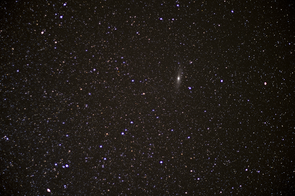 Andromeda: Pentax K-3, 50mm SMC-M, 100-second Exposure
You'll need to practice this and likely fine-tune your articulating board's angle. Using the tape to mark the threaded support rods' nuts' positions will allow you to start.
Calibrating your barn door tracking is best done through trial and error with a DSLR. Set up your DSLR on the tripod head and place your pole star in the center of your frame. A 50mm lens is ideal for this. Use bulb mode and use a remote control or cable release to toggle the shutter.
Start your barn door tracker and let it run for about 15 seconds to help any start-up shakes get out of the system. Start your exposure. After your exposure, if the stars are fine dots, then you've placed your barn door tracker correctly.
In the real world, you will not have placed your barn door tracker correctly. If the trails from the stars are very short, then you've placed the trackers well. Because the pole star won't appear to move, we can use it to calibrate the barn door tracker. Knowing that that pole star should be motionless and that the camera was moving in a counter-clockwise arc, you can gauge how far off the tracker is.
If your star trails seem very long for the exposure duration, your battery is probably set to the wrong polarity. Switch the alligator clip connections on the motor and try again.
If your star trails move up and right, your barn door tracker is off-axis with the pole star. Try moving the tripods but keeping all your other settings correct.
If your star trails are short and move up and left, your articulating board's angle is too far off. Try adjusting your articulating board angle by rotating the nuts on the threaded support rods.
Once you have your tracker calibrated, the sky is your oyster. No matter where you point your camera, you will obtain shake-free images. This allows you to take long-duration exposures of multiple minutes. Using a DSLR, I have managed shake-free images up to 368 seconds (and could have managed longer images had I brought a second battery.) Using film, I've managed images up to 15 minutes. This allows incredible detail and color at low sensitivities. The picture below is the longest digital exposure I've attained with an astrotracking device, and was shot at ISO 400.
 Milky Way: Pentax K-3, Samyang 10mm f/2.8, 368-second Exposure
References
More from the Pentax Forums Homepage
- March 2024 "Flowers up Close" Photo...
- Ricoh updates the K-1, K-1 II, GR III, GR IIIx
- March "Flowers up Close" Contest...
- HD FA 50mm F1.4 vs. SMC 50mm F1.4 Classic Review
- Announcing Our April, 2024 Photo Contest
- Introducing Pentaxify AI by PentaxForums.com
- The Making of "Autumn Draws"
- Ricoh launches the RICOH GR III HDF and RICOH...

Tags
astronomy, astrophotography, astrophotography series, astrotracer, barn door tracker, log exposure, night sky, sidereal tracker, star tracker, stars

Comments