| Pentax/Camera Marketplace |
| Pentax Items for Sale |
| Wanted Pentax Items |
| Pentax Deals |
| Deal Finder & Price Alerts |
| Price Watch Forum |
| My Marketplace Activity |
| List a New Item |
| Get seller access! |
| Pentax Stores |
| Pentax Retailer Map |
| Pentax Photos |
| Sample Photo Search |
| Recent Photo Mosaic |
| Today's Photos |
| Free Photo Storage |
| Member Photo Albums |
| User Photo Gallery |
| Exclusive Gallery |
| Photo Community |
| Photo Sharing Forum |
| Critique Forum |
| Official Photo Contests |
| World Pentax Day Gallery |
| World Pentax Day Photo Map |
| Pentax Resources |
| Articles and Tutorials |
| Member-Submitted Articles |
| Recommended Gear |
| Firmware Update Guide |
| Firmware Updates |
| Pentax News |
| Pentax Lens Databases |
| Pentax Lens Reviews |
| Pentax Lens Search |
| Third-Party Lens Reviews |
| Lens Compatibility |
| Pentax Serial Number Database |
| In-Depth Reviews |
| SLR Lens Forum |
| Sample Photo Archive |
| Forum Discussions |
| New Posts |
| Today's Threads |
| Photo Threads |
| Recent Photo Mosaic |
| Recent Updates |
| Today's Photos |
| Quick Searches |
| Unanswered Threads |
| Recently Liked Posts |
| Forum RSS Feed |
| Go to Page... |
PentaxForums.com → Camera Help Central → Pentax Articles → Maintenance and Repair Articles
→
Repair and Restoration Pentax 67
 |
| 6 Likes | Search this Thread |
| 3 Likes | #1 | ||
| |||
| Views: 16,604 | |||


Aristote | |
 | View full profile |
| Contact via private message | |
| Find other posts by Aristote | |
| Find threads started by Aristote | |
| Find threads in which Aristote has posted | |
| These users Like Aristote's post: |

| 03-19-2020, 03:57 PM | #2 |
|
It looks like an adventurous undertaking. I didn't realize there was so many gears, cams and linkages under the skin. The link to the manual is broken, btw.
| |
| 03-19-2020, 03:59 PM - 2 Likes | #3 |
|
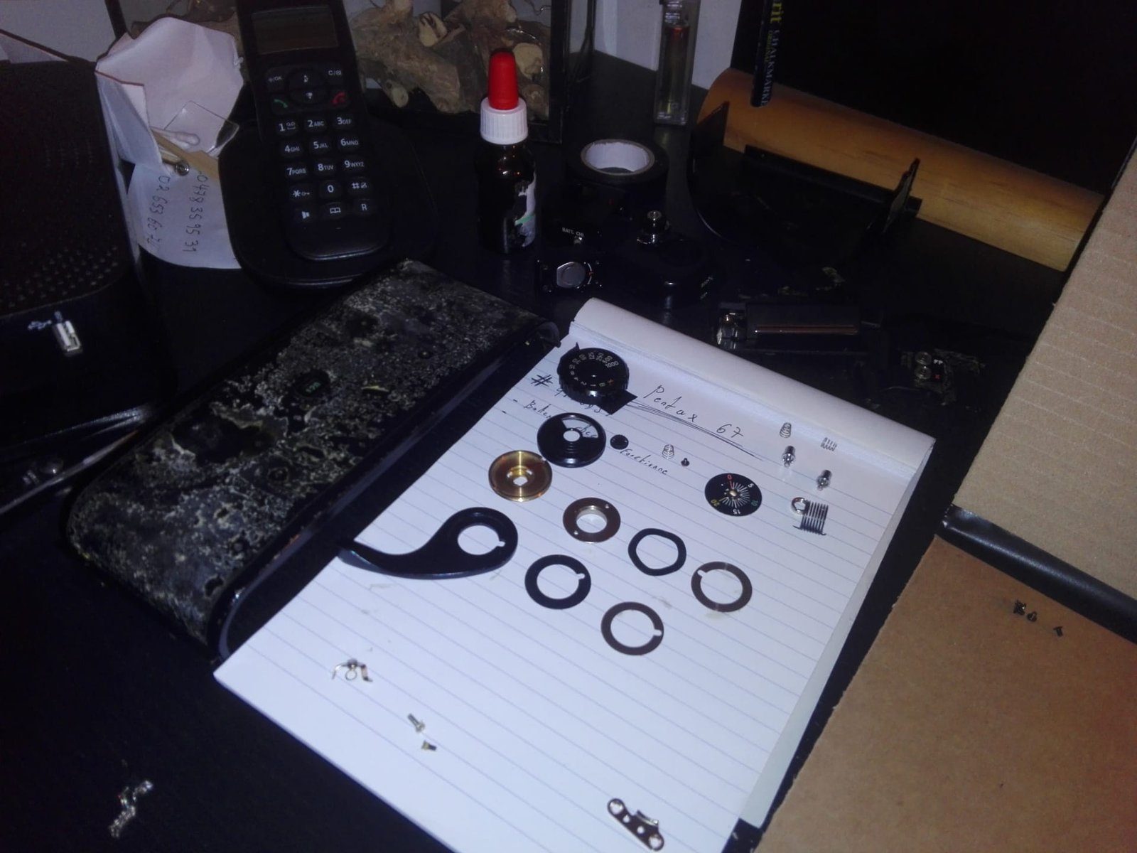
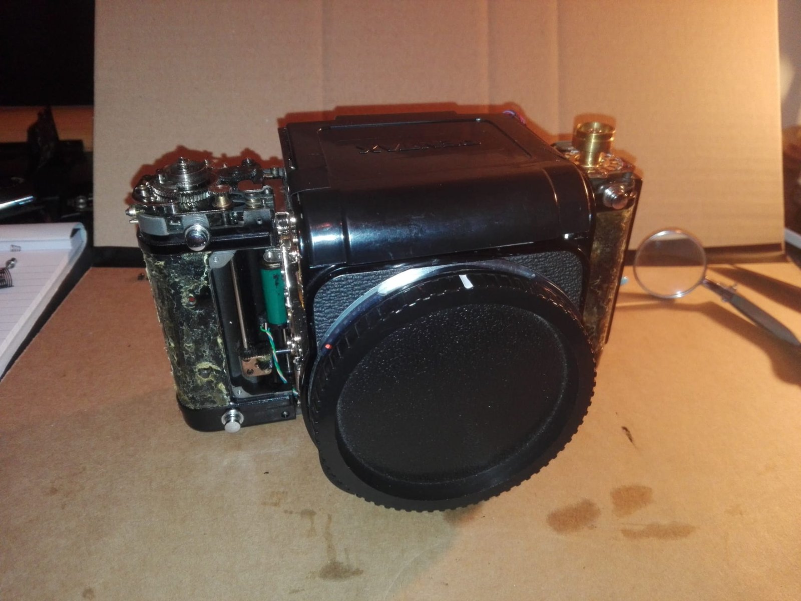
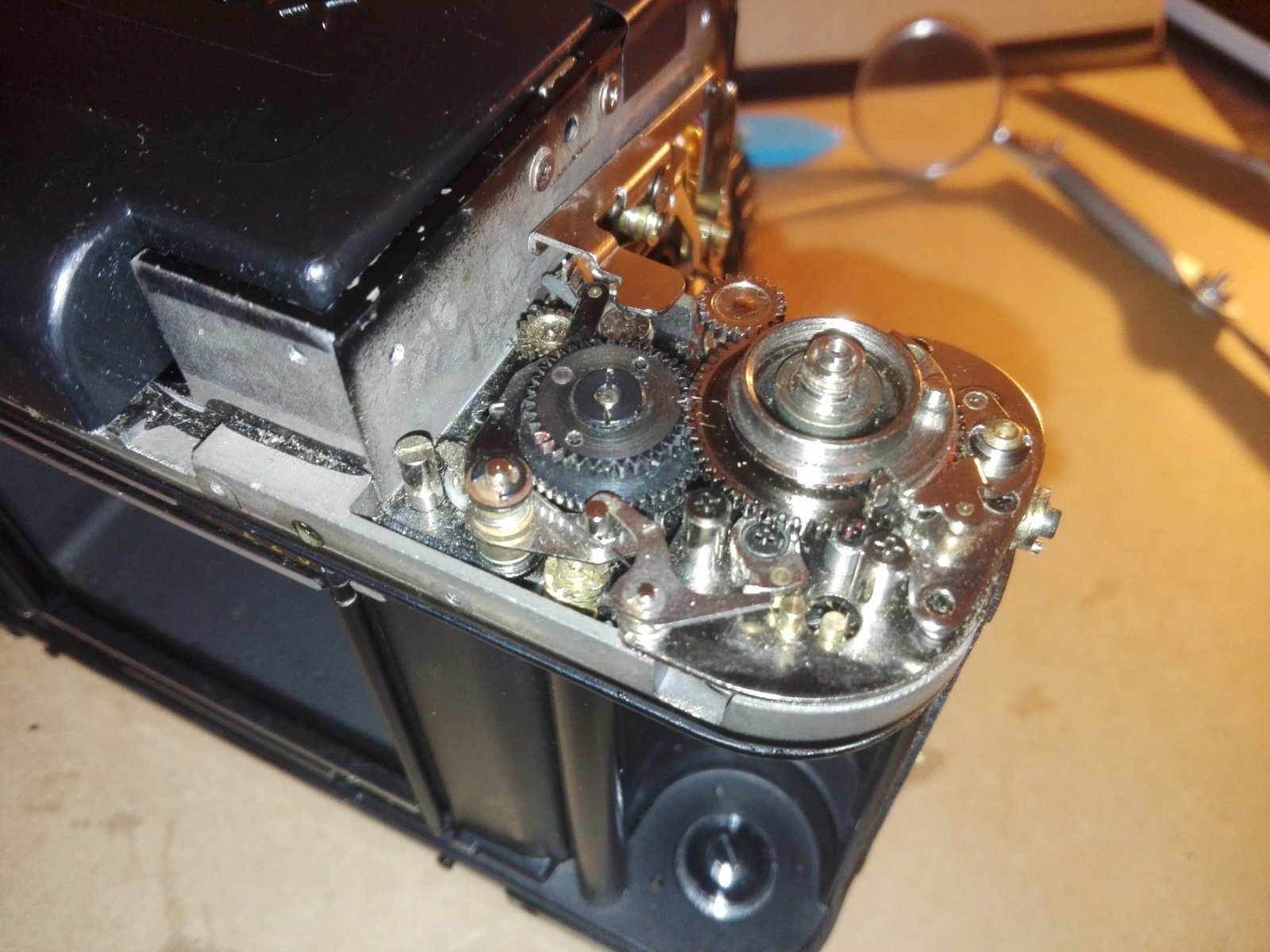
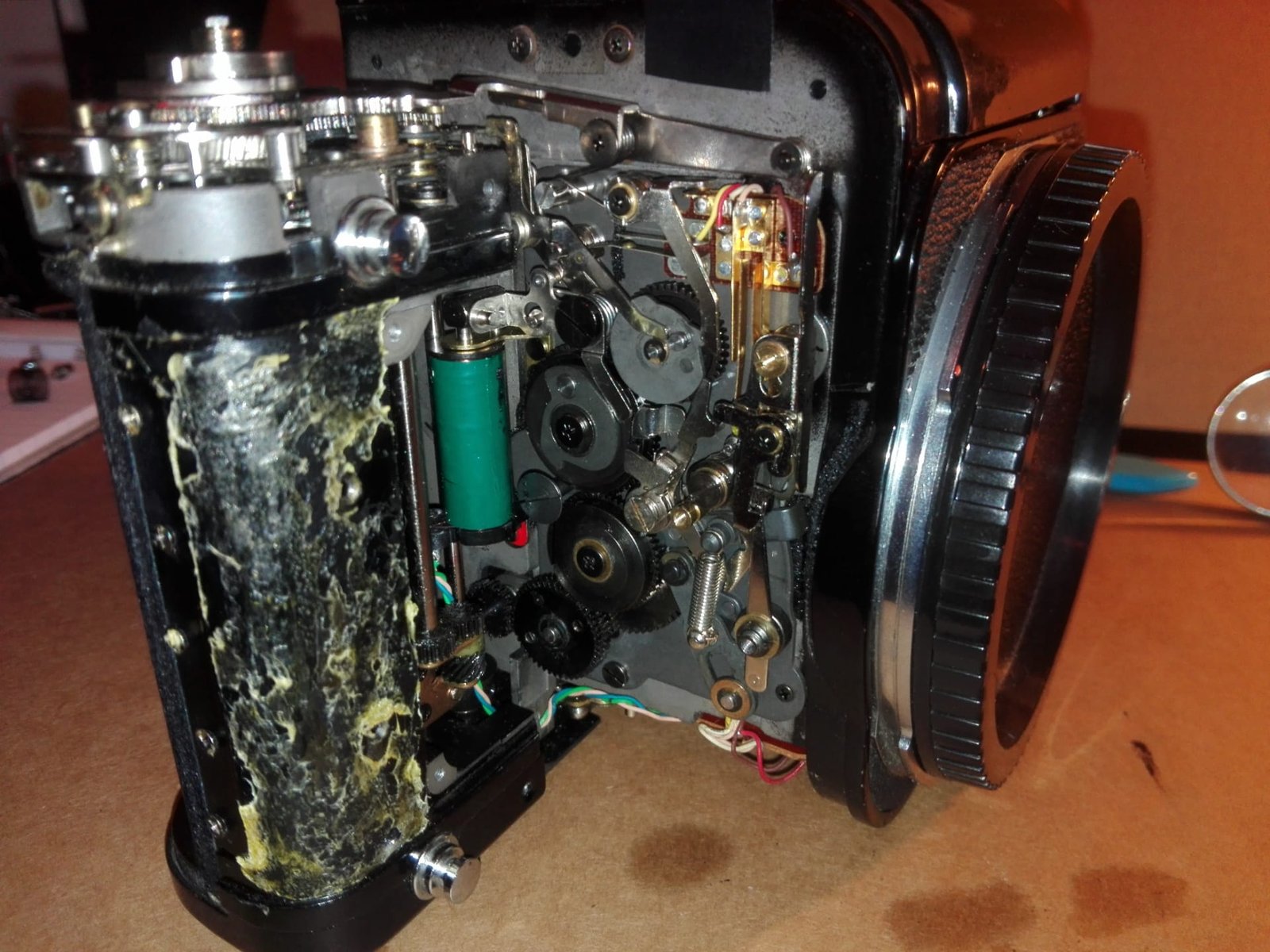
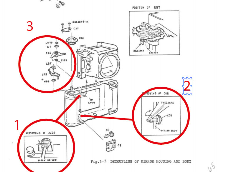
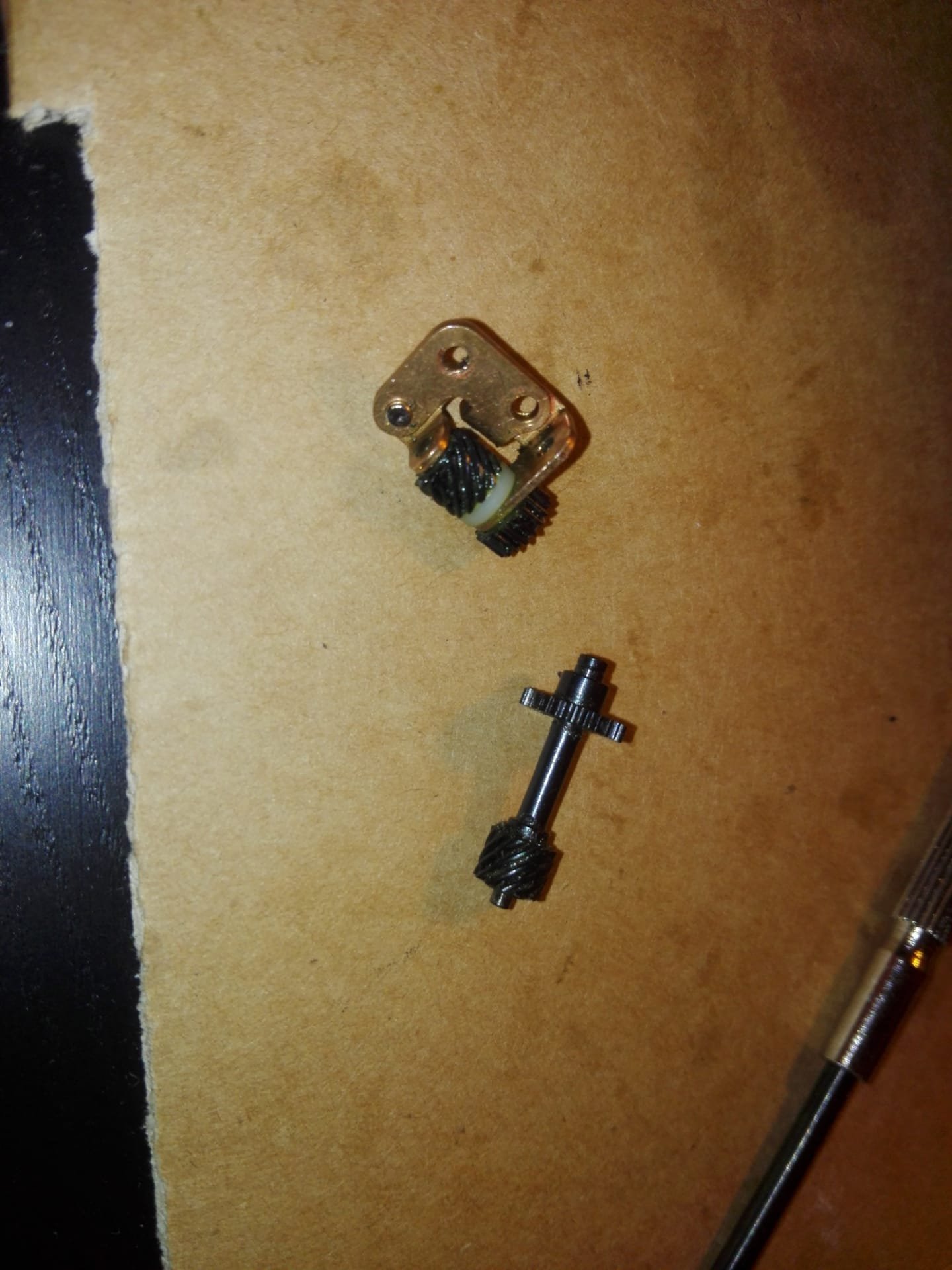
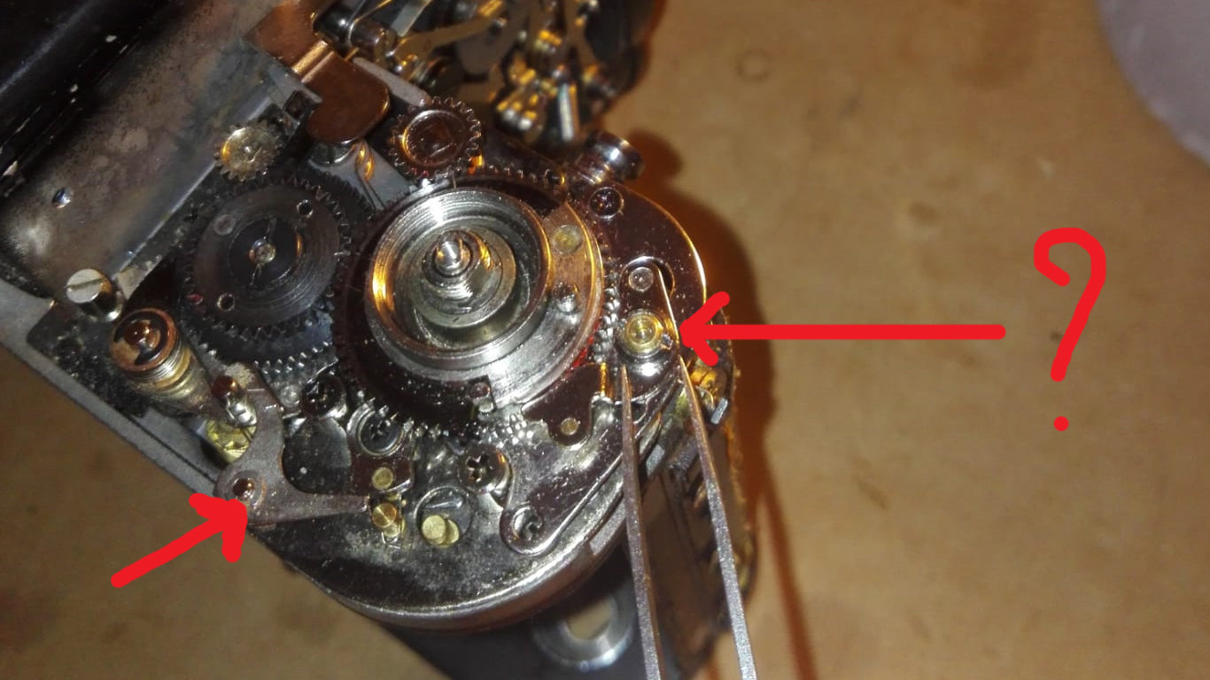
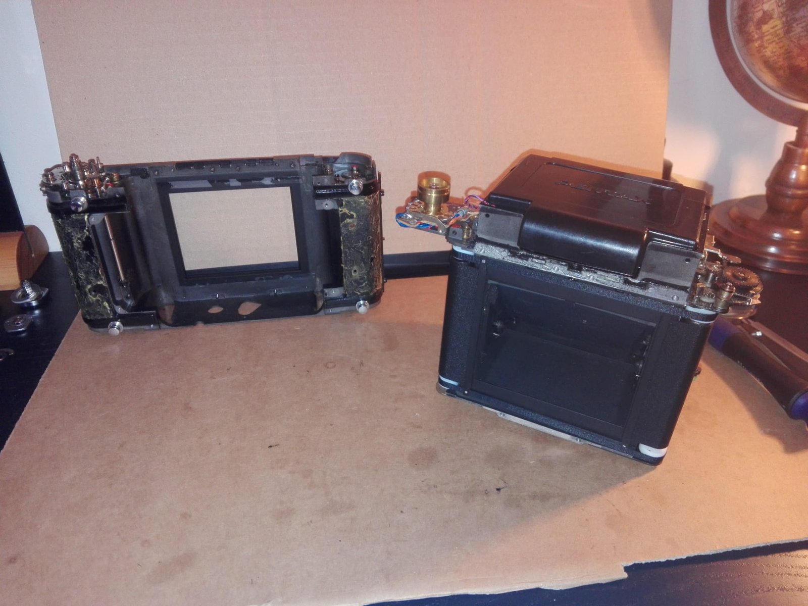
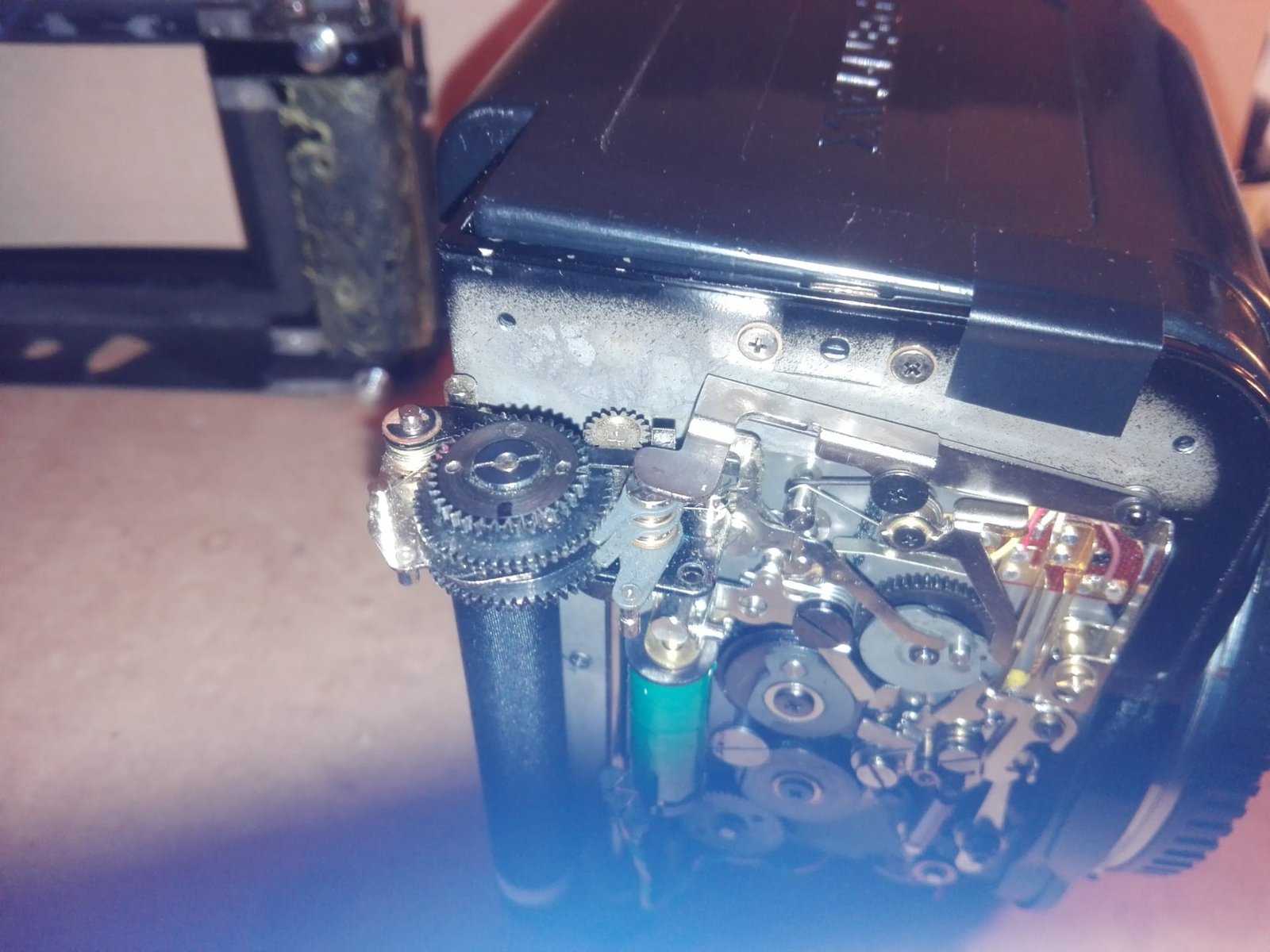
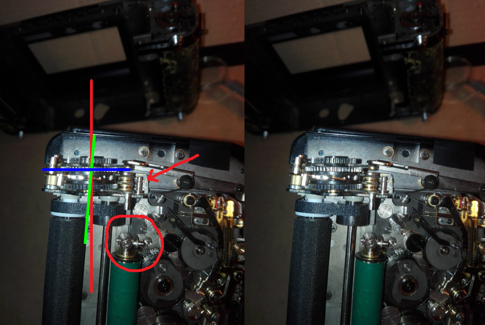
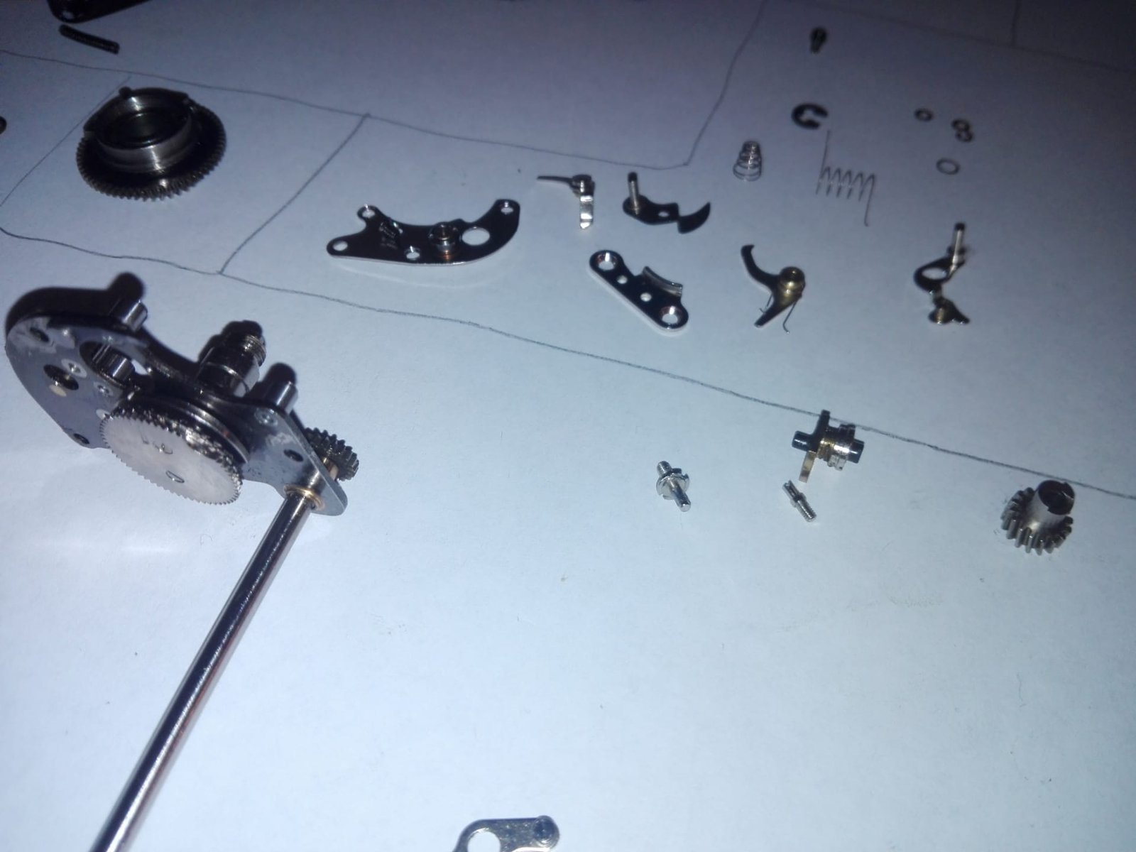
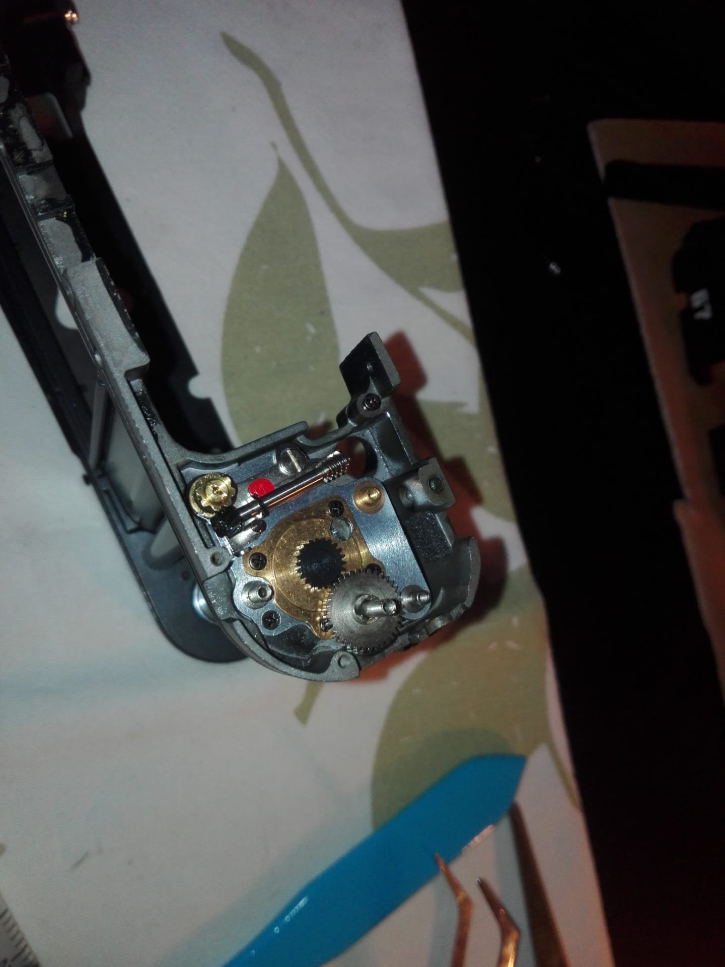
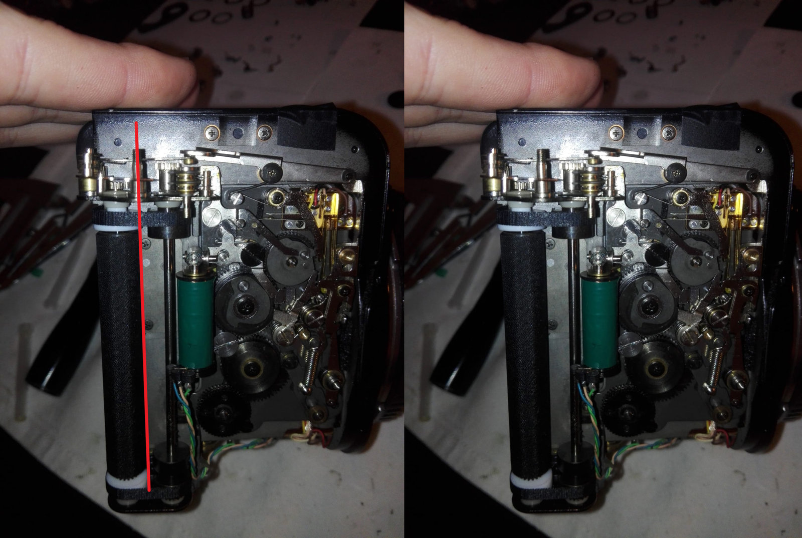
Continuation of the operation on the cage. After having straightened and cleaned the axis and the supports, I also made a small inspection tour and I noted that foams were present on the points in photo. In addition, I took the opportunity to clean, oil and grease the mirror mechanism which was relatively clean, but whose old greases had disintegrated over time. Classic cleaning with 70 ° alcohol and cotton swab on the shafts and cams. We will avoid touching the contact blades as Oriu told us, at the risk of distorting correct operation. Then, we will grease and oil the friction points with a micro brush and syringes loaded with consumable while following the instructions in the service manual. Pentax uses different types of grease for its maintenance. 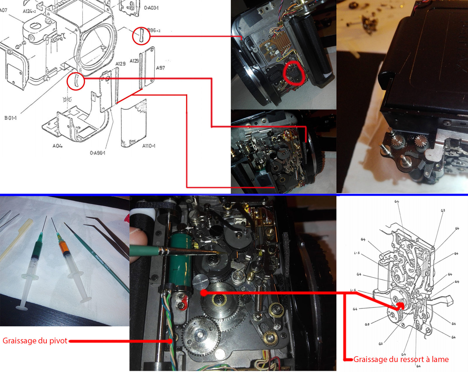 During the calibration of the shutter, I noticed that the locking lever was not in contact with the pinion of the first curtain, so I had to straighten the axis again to make it coincide. To be more precise in the operation, I measured the spacings with a set of gauges. The first measurements gave: 0.60 mm => 1st curtain 0.30 mm => 2nd curtain Which is a huge difference for such small parts. Lest the game worsen over time, I continued the recovery by going in small strokes on a dozen interventions (you have to go smoothly, it's brass). The final measurement: 0.40 mm => 1st curtain 0.30 mm => 2nd curtain We are in something more acceptable now. 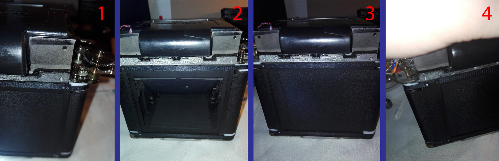 The curtain was too far of the edge on the point 2. If the curtain is too far, when you cocking the shutter, the gear can't take the shaft correctly and problem coming. We are moving slowly, but surely! I repositioned the upper plate of the arming mechanism (0-C34) successfully, I think, the rest will wait while waiting to reassemble the cage on the chassis. Indeed, it will be easier to couple it this way. 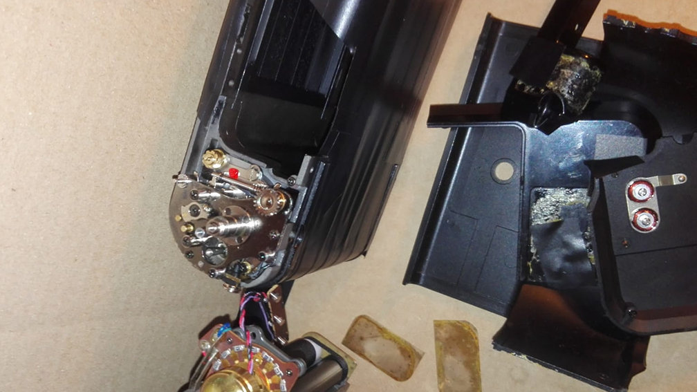 I also started the repair of the prism coupling chain with the housing. As we can see, the spring is completely destroyed by inappropriate tension. Following an aberrant fragility of the original coupling chain, I decided to replace it with a 0.25mm diameter nylon thread. If you need to do this, I recommend replacing the chain completely with this type of wire. It is much more resistant and stable in drive pulleys. However, the spring is so destroyed that it releases the wire each time it is mounted. I will come back to this at the end of the process so I have just changed the foams for now. 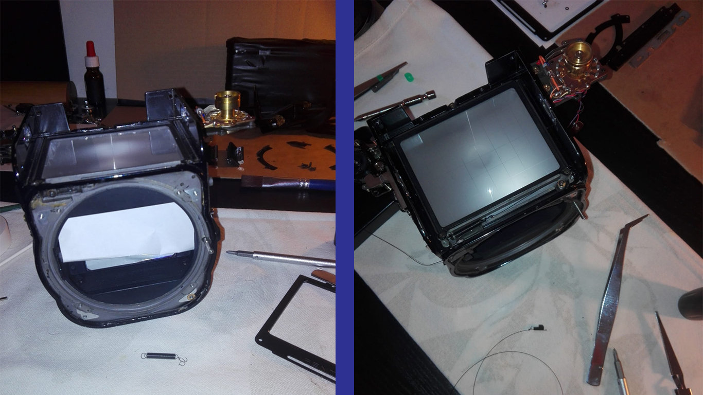 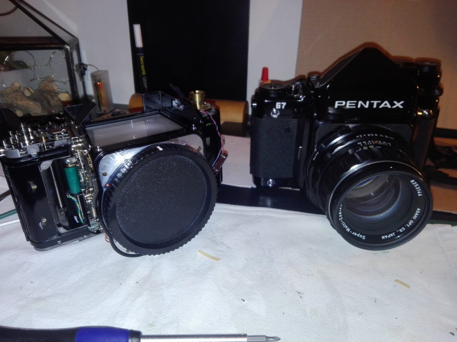 There is a problem with the frame counter dial. I dismantle the part to see the problem inside. The spring was gone on the wheel, so I re mount it, but when I turned the wheel, the spring was destroying :/ 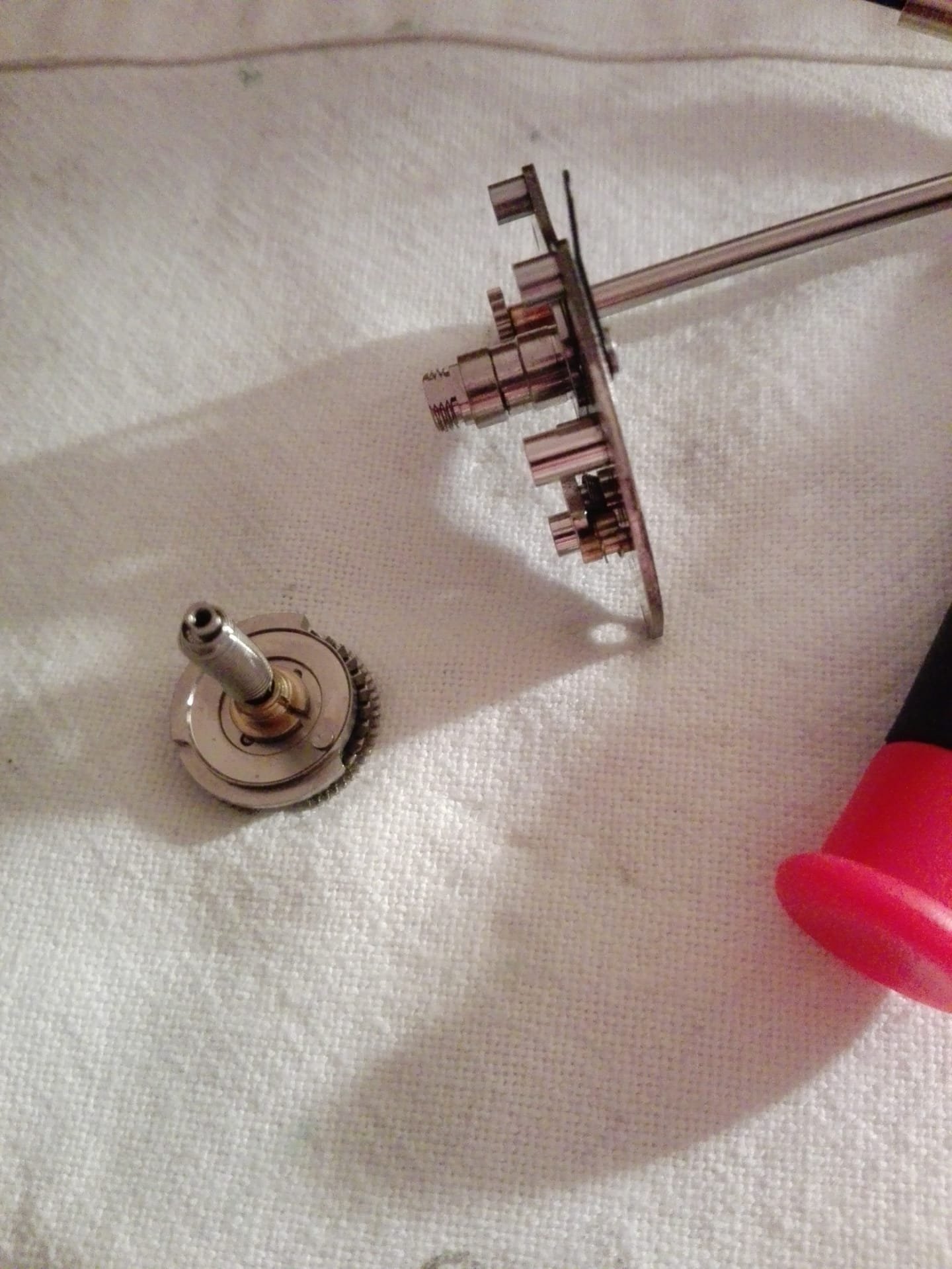  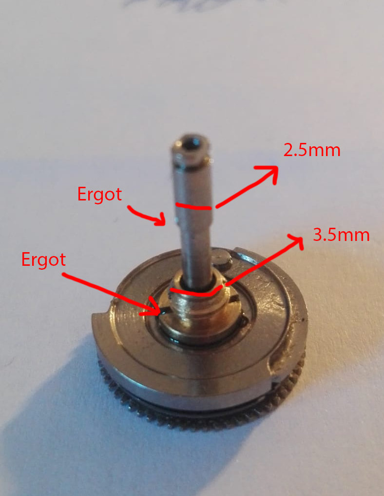 I was lucky cause Remy on the Forum sent me new spring of Kiev 88 and VHS player ! Thanx so much again <3 After reassembling the mechanism, I encounter the same problem as at the beginning. The mechanism arms the shutter and the mirror, moves the film to the first view, stabilizes it, the shutter exposes the view. Then, the successive armings only arm the mirror and the shutter, but the film does not advance further, it remains on the first view counter does not advance further. Observed facts: - The view counter does not reset when I open the door. I must remove the O-C33 plate and therefore the O-C24 cam so that it returns to its starting position ( fig 1 ). - On my functional unit, I note that when I rotate the winding pin C48 in the loading direction, a rattling occurs by the jump of the pinions C43 and C44 ( fig 2 ). Clicking that there is no faulty case. - The friction spring in C118 ( fig 3 ) seems to no longer play its role. When I removed the film, it comes easily in the blocking direction by pulling it. I had inspected it briefly before reassembly and it seemed to work at the beginning ... I suspect the friction spring, but why does it cause the film on the first view if it is broken ? 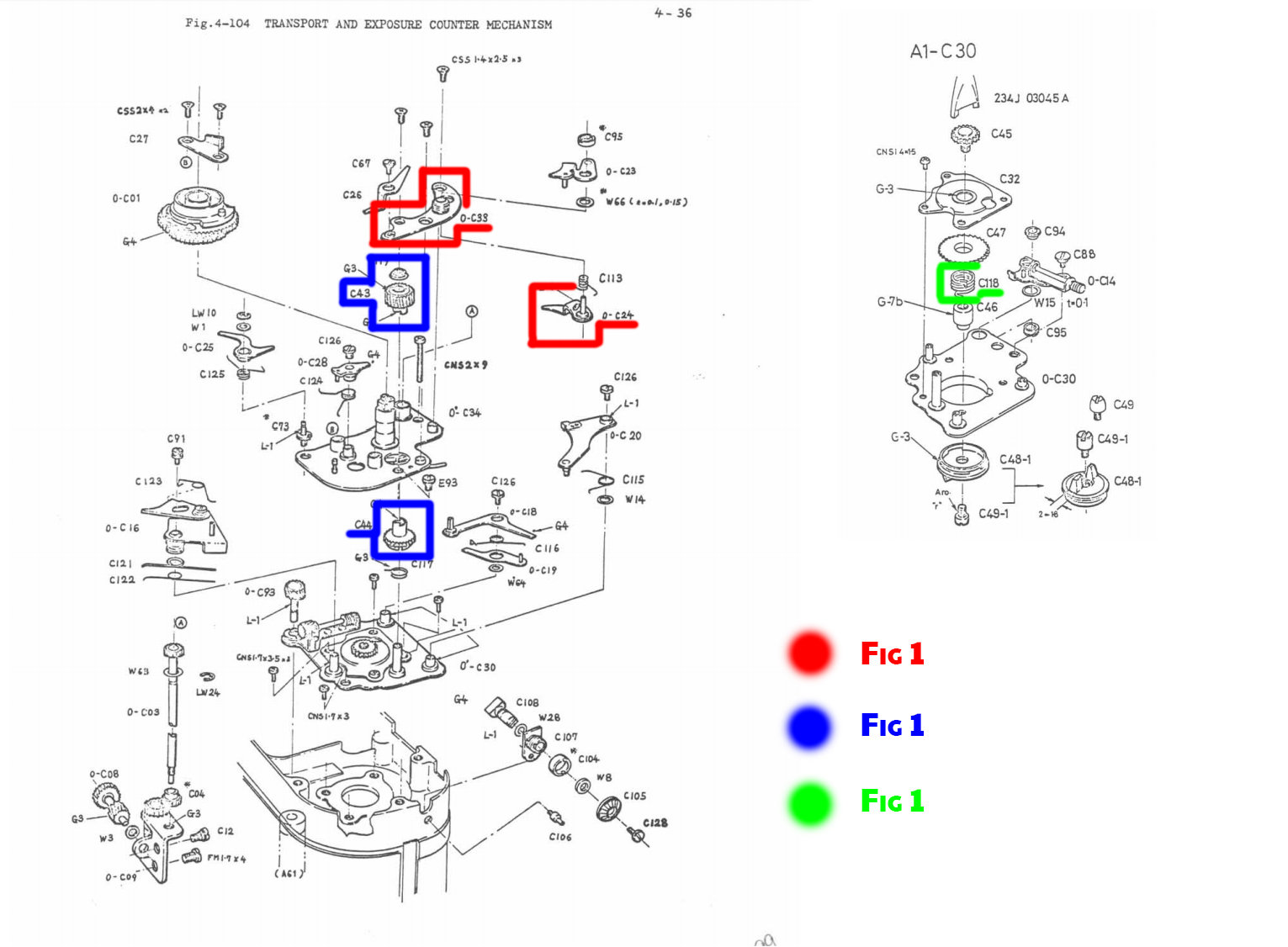 My mistake ! It was indeed the friction spring located between the winding lug and the transmission gear. It allows the good winding of the film by forcing the direction of it in one direction only. We see on the video that the film no longer advances if we maintain a slight pressure at its base. Re re re re complete disassembly of the mechanism, but not going any further this time. I had to put down the first plate which contains the spring, but the screw which holds the assembly is very soft and did not hold the shock. I'm going to have to work on a way to extract it, I will run a new one later. First bath in WD-40 to facilitate the process, then I will think about the best way to extract this spring dirt C118 with a special tool. 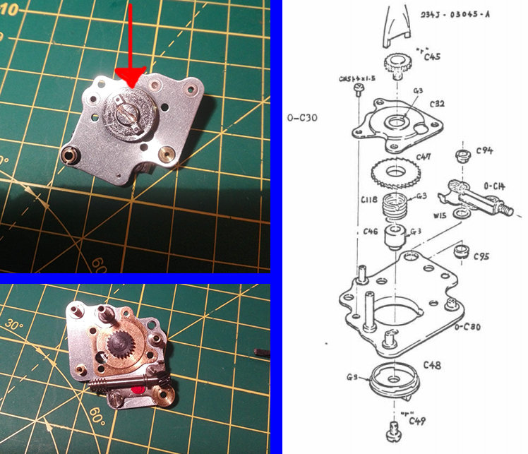 After 48 hours of WD40 bath, it remains tough this little screw! I was surprised by the amount of dirt that bleed from the cavity, probably a mixture of grease dust ... We can see the state of the WD40 on the attached image. Disassembly was done with a rectified screwdriver and a caliper whose chevron spouts adapt perfectly to the gear. Unfortunately, without success : cry: It will leave for 48 hours more in the pool, it will give me time to machine a more precise tool to avoid the nonsense that could occur, the caliper is quite large and does not allow maneuverability optimum. This small room makes me particularly anxious ... The composition of the tray does not reassure me at all ... To be continued ! 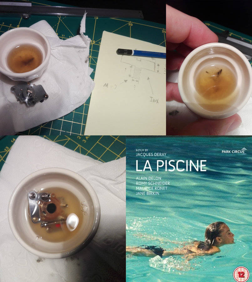 Not without difficulty, I finally dismantled the group. The thread is reversed and the thread lock was present which did not facilitate its removal. I had to rectify and enlarge the impression of the screw head. The tightening torque was really strong and the screw material quite soft, which does not help of course. The spring appears to be in good condition. The only explanation would be that a fatty substance accumulates in the cavity and interferes with friction. I cleaned everything with a fine brass brush followed by a Trichlorethylene bath. I noticed a lot of dross coming out of this small group, it was quite impressive ... If the problem persists, I do not see where the failure could come from ... Cross my fingers ! 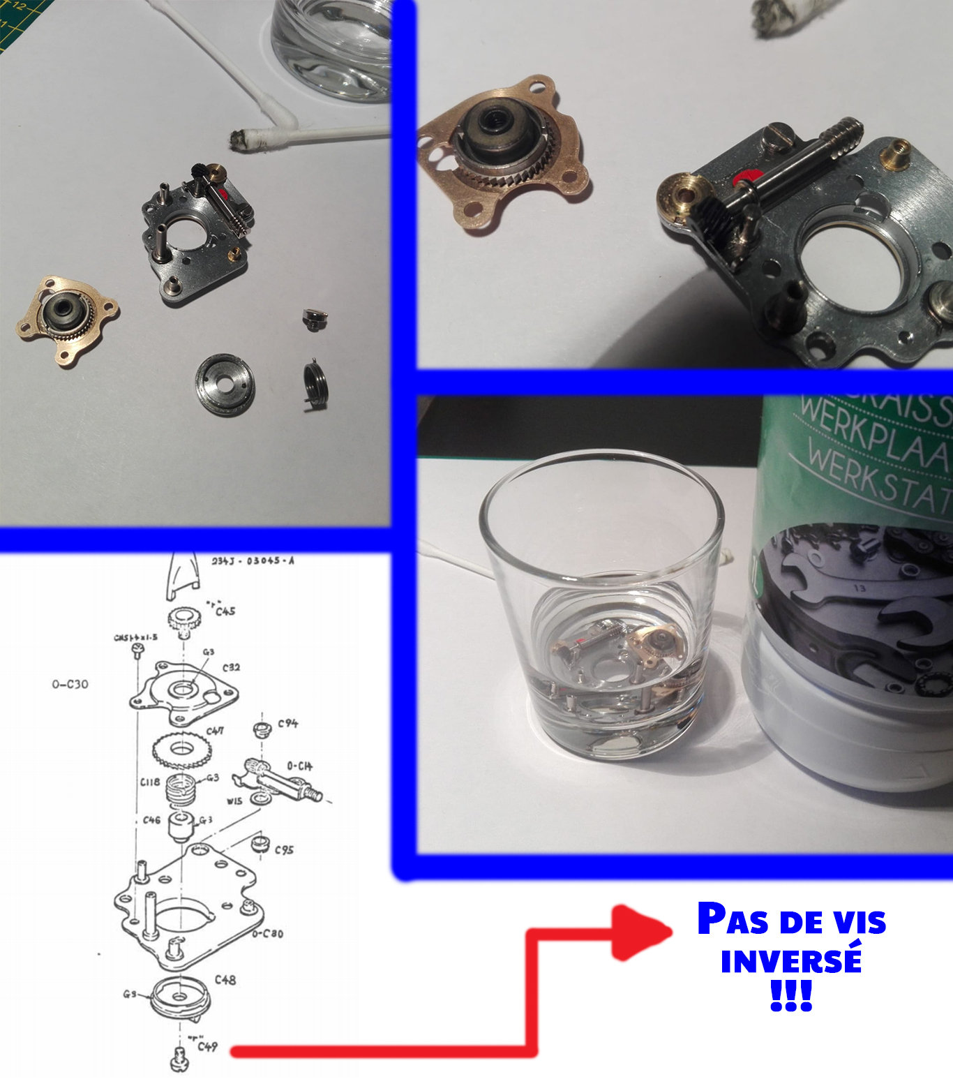 To be continued... ---------- Post added 03-19-20 at 04:00 PM ---------- Hi Tuco ! Here you are : ASAHI PENTAX 6X7 SERVICE MANUAL Pdf Download. ---------- Post added 03-19-20 at 04:08 PM ---------- So ! The spring of counter dial frame is repaired with new spring. The Camera is repaired but not completly, the shutter work and the mirror too, but the transport film not. I'm gonna check this part with the friction spring. Stay tuned ! | |

| These users Like Aristote's post: |
| 03-20-2020, 08:21 AM | #6 |
| Loyal Site Supporter    |
Nice. Seeing that camera in hand makes one realize just how huge it is. That actually makes me want one more. I wonder if I could set one of my auto 110 cameras in the bayonet mount?
|
| 03-20-2020, 09:07 AM | #7 |
|
Nice work. | |
| 03-20-2020, 09:21 AM | #8 |
|
Thank you for your compliments! He remains capricious ... But he returns from darkness so it's normal. Folded axis of curtains, detached spring, serviced and folded control cam, etc. Lots of little things that make a big deal of trouble ! I'm not out of the tunnel yet... This an exceptional camera ! I prefer it compared to the RZ which is also good, but its modularity which is a big quality becomes a big defect in my hands (slower loading of the film, bigger, different ergonomics). If I have the opportunity to find a third Pentax, I will take it without hesitation ! | |
| 03-20-2020, 01:28 PM | #9 |
|
Impressive! Looking forward to next part of the story (... and the camera lived happily ever after  | |

| 03-20-2020, 02:33 PM | #10 |
 Impressive! Looking forward to next part of the story (... and the camera lived happily ever after I have two screws to machine before returning to the Pentax. I am trying to repair this camera without cannibalizing another Pentax 67. I assume that they are repairable and that putting them in the trash for donors is an aberration. Therefore, it takes a little more logistical time. I am going to test painting, but with COVID19 the paint stores are closed. | |
| 03-24-2020, 03:32 AM | #11 |
|
Thank you very much for your contribution! I linked this one to the broken Pentax 67 Repair (missing pictures), because the search still gives the other out more easily. I hope to see your 67 soon up and running again!
| |
| 03-24-2020, 04:58 AM | #12 |
|
Hi Wildmo ! Thanks so much for linking ! I hope so too ... With the Covid19, the process is a bit halted so ... I resume the operation as soon as I can | |
| 03-29-2020, 01:36 PM | #13 |
|
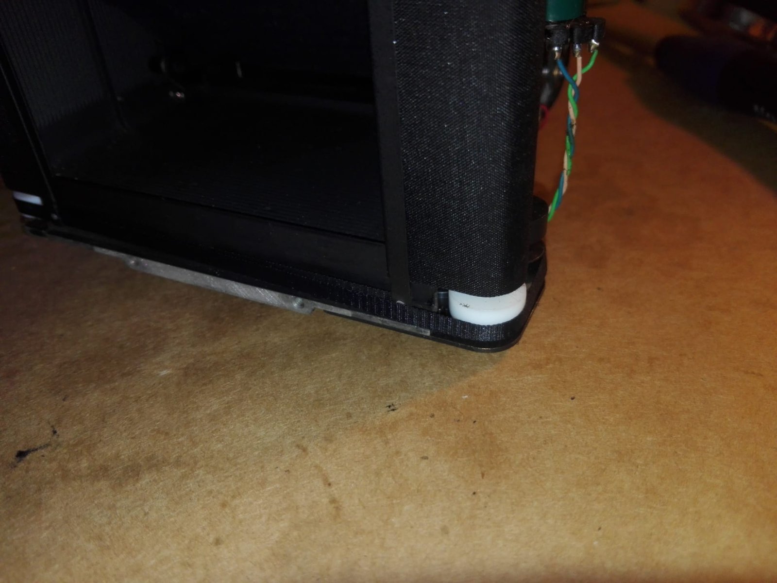
Well ! With containment the restoration is slower, but I finally wanted to try the paint and started sanding the plates below to redo a paint. The Rubicon is crossed. The upper ones are in good condition and I will not touch them. The former owner used to use a dedicated handle and caused friction damage. 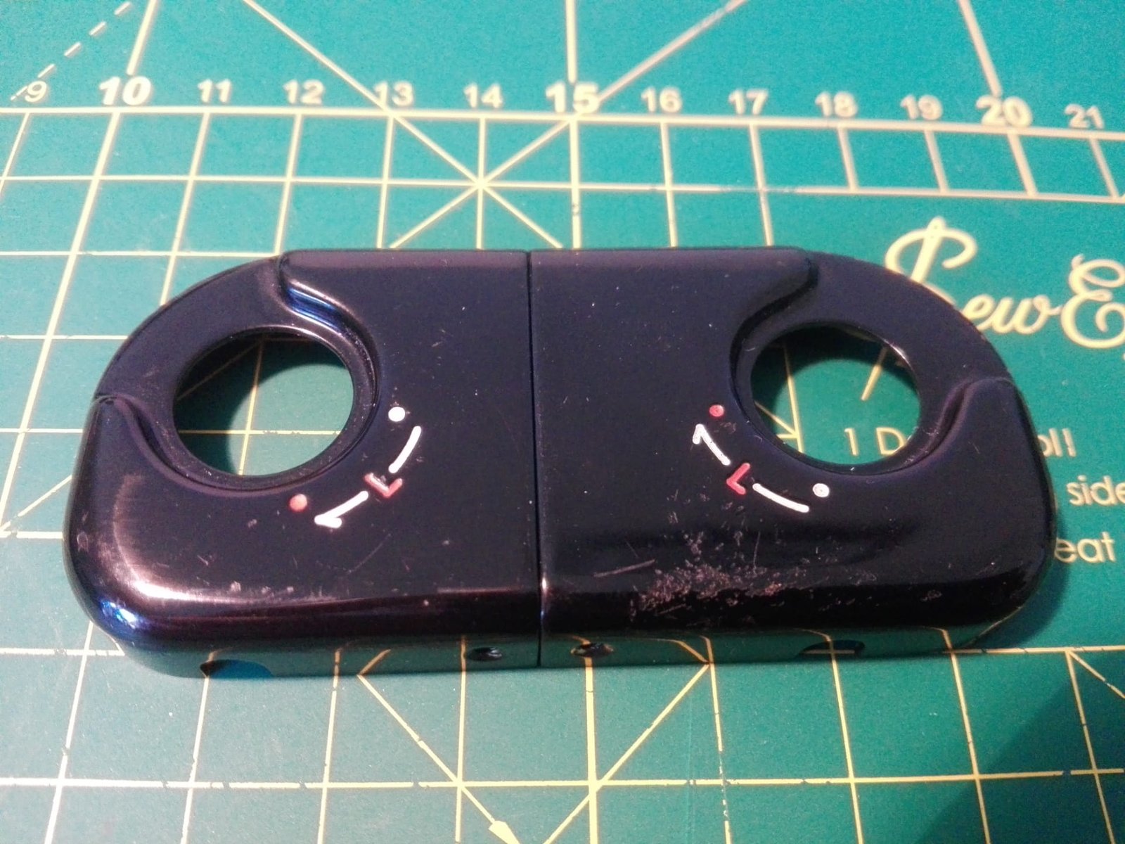 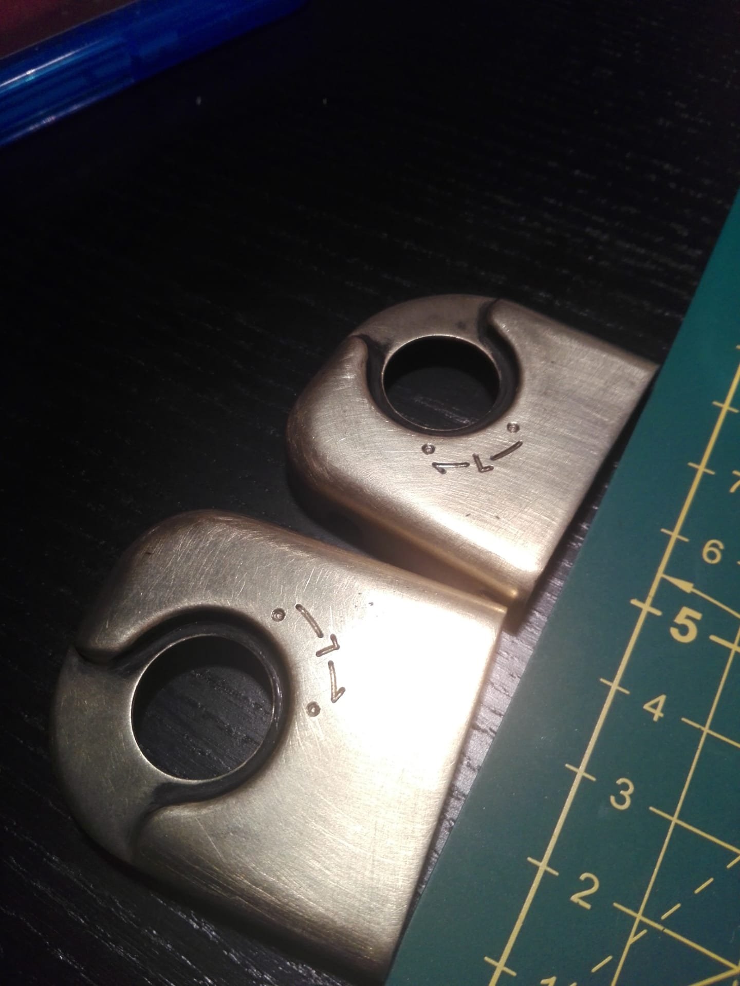 In addition, I give you a little tip if your battery compartment is lower than the protective plate. Just place a shim and bend the leaf springs.  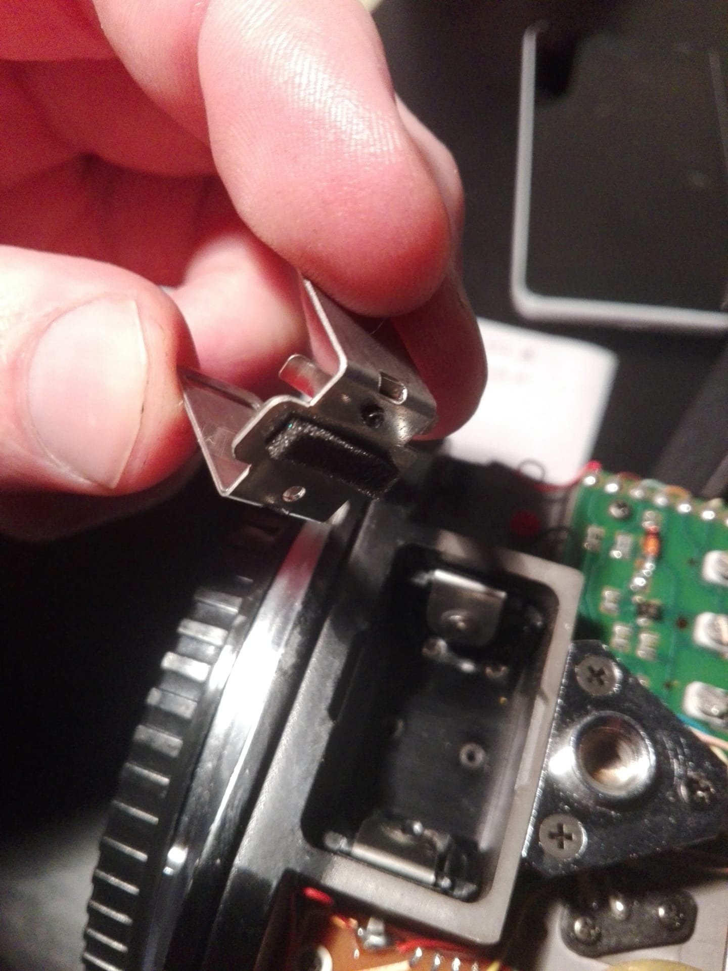 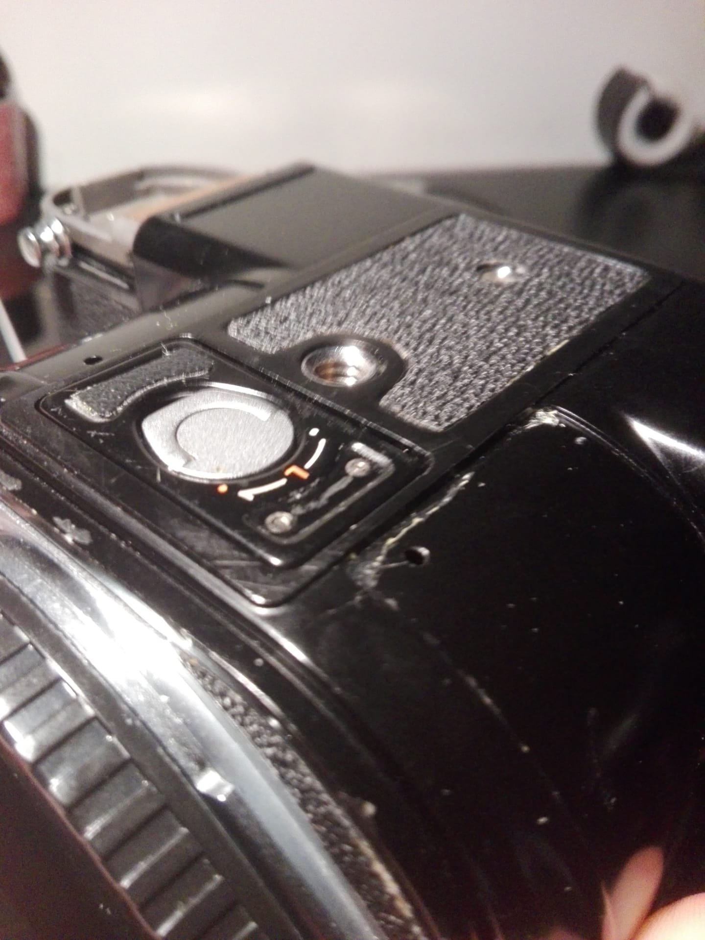 | |
| 04-23-2020, 02:18 PM | #14 |
|
A little new in the progression ! The original caches have lived a lot and are likely to spoil the paint job .... I therefore decided to design new protective caches for the Pentax 67. As you know, I decided to repaint the rear door rails and the brass soles. I will not touch the top covers because, as Oriu pointed out, they are in good cosmetic condition. So I started modeling new caches which I will have 3D printed then smoothed with acetone in order to obtain the original gloss of the old polycarbonate sheets. I would have liked to machine them out of steel or aluminum, but the CNC costs in private are completely outrageous ! I could try to see if the digital milling machine is accessible at my old college. Whatever happens, 3D printing will remain the preferred solution. I tried to reproduce the dimensions and dimensions of the right side cover as faithfully as possible (front view), there will surely be several tests to do and small corrections here and there, but the bulk of the bulk is done! I purposely excluded the holes for the flash connections for three reasons: 1) I never use flash. 2) The flash at 1/30 of the Pentax, hum hum ... 3) It looks prettier like that. It should be noted that in the worst case, the holes may be machinable using a few drills ... We always keep an option. The structure has been reinforced with an addition of material at the edges in order to increase the resistance of the cover and to leave a margin for drilling the fixing holes. I added two cavities of 5 mm in diameter so that the screws of the ratchet can accommodate without bulging the plastic. Here are some illustrations while waiting for the modeling of the other parts:   I do not think to make the plate above the back which is in good condition. On the other hand, the lower cover would also need to be redone, but modeling it is sport ... Stay tuned ! PS : Example of final result 3D print smoothing  | |
| 05-01-2020, 04:28 PM - 1 Like | #15 |
|
I finally launched the modeling of the bottom plate, it wasn't easy on Autocad, but with some tutorials and a lot of patience everything is possible ! I will obviously make the files available for free download, but I must first check if the measures are well suited to the body.    | |
| These users Like Aristote's post: |
|
« Modding Chinese (and other) tripod mounts to fit eg adaptall lenses
|
Cross-head screws - a caution: »
| Bookmarks |


| Tags - Make this thread easier to find by adding keywords to it! |
| 1st, axis, cage, cam, chain, curtain, elements, grease, head, mechanism, mind, mm, oil, operation, pentax, pm, post, restoration, screw, screws, service, time, tools, view, wd40, wheel, wire |
| Top Liked Posts |
3  Post #1 by Aristote Post #1 by Aristote |
| 2 Post #3 by Aristote |
| 1 Post #15 by Aristote |
 Similar Threads
 | ||||
| Thread | Thread Starter | Forum | Replies | Last Post |
| Pentax 67 - Restoration Project | tomart | Maintenance and Repair Articles | 35 | 03-24-2020 03:33 AM |
| New adventure: KX restoration? | ismaelg | Film SLRs and Compact Film Cameras | 27 | 01-14-2020 07:30 PM |
| Why stop motion car restoration is Youtube the hard way | interested_observer | Photographic Technique | 6 | 10-30-2019 10:54 AM |
| Lens body restoration. | Prince Harbinger | Pentax SLR Lens Discussion | 7 | 03-11-2019 04:56 AM |
| Photo Restoration | bmeiri | Mini-Challenges, Games, and Photo Stories | 2 | 06-08-2013 02:50 AM |


