Forgot Password
Pentax Camera Forums Home
 

Reply
Show Printable Version 22 Likes Search this Thread
12-17-2016, 08:34 PM - 14 Likes   #1
New Member


Join Date: Jan 2013
Location: New England
Posts: 2
K-30/K-50 Aperture Control Problem/Black Photo Repair - How I did it.

After sitting idle for a few months, I fired up my K-30 to find it was taking black photos only. After some basic troubleshooting, it was obvious that the aperture was closing down all the way, no matter what the camera said it should be. So some internet searches led me here because it seems the only technical article is from a Russian site. One of the members here was good enough to translate it for us, so at least I had a basic understanding of what to look for.

Since I have a long background in electronics troubleshooting and working on small delicate items, I decided to dig into my K-30. It was useless and not worth anything as it was, so what's to loose? Here I'll explain how I did it, and maybe help others that find themselves in a similar situation.

So let’s get started. For the sake of clarity, the right and left sides of the camera are when viewed from the front. Also, work with a body cap to protect all the innards, and keep small parts from flying in there.

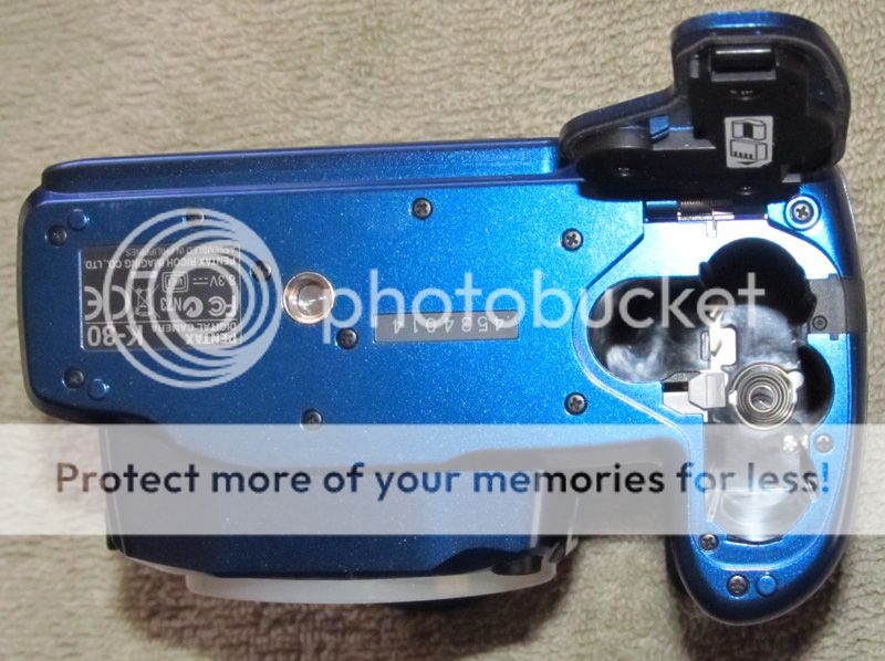
1) Remove the bottom plate: Remove all the screws holding the bottom plate. Make careful note of which screw came from which hole. Some screws are fine thread for metal and some are coarse thread for screwing into plastic. There are 3mm, 4mm, 6mm, 7mm and 10mm screws. While you’re at it don’t forget the silver screw down inside the battery compartment. There is a total of 13 screws.


2) Remove the top cover: WARNING: (I hate stupid warning messages, but this IS important, so DON’T take it lightly. The flash capacitor is directly under the PCB that you will be desoldering wires from on the right side, and areas near the PCB do have some “juice” that can give you a NASTY JOLT – one you won’t forget! Be very careful).

Slide the rubber eyepiece up to remove it. There are 2 screws under it that need to be removed. Remove the 2 screws just inside the loops for the neck strap. There is another screw on the right side just under the button for the pop-up flash. Now pop up the flash and remove the 3 screws inside the front. There is a total of 8 screws. The top cover is not difficult to remove at this point. A thumbnail pressed into the top cover seam is all that is needed to get it started. Be gentle. If you pull too hard and it suddenly pops off, the wires inside will most likely get ripped off their solder pads. There is a total of 6 wired to be unsoldered.

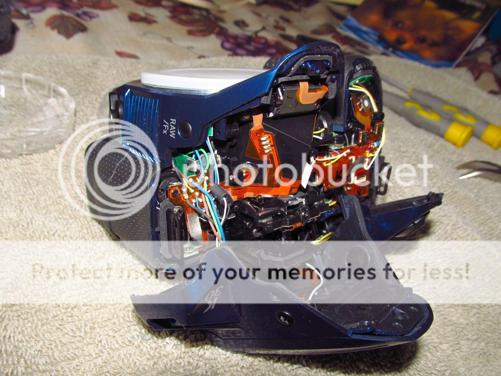
3) Unsolder the wires from the PCB on the right side. Position the camera as shown below to minimize the stress in the wire leads. Make note of their locations and unsolder them. (Remember that warning above????)

4) Remove the ribbon connector on the left side.


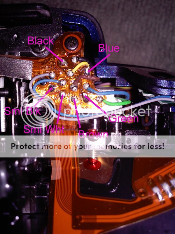
5) In case you lose track of where the wires go, this should help.

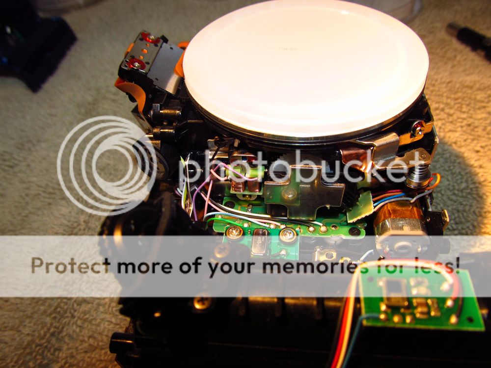
6) Remove the front cover: Remove the rubber grip on the right side of the camera. There are 2 screws underneath. Peel back the left rubber grip slightly and remove the first screw that appears. Lay the rubber back down – there is no need to remove it. Remove the other screw on the left side near the DC power jack. There is one more screw on the bottom between the projections for the lens and hand grip. There is a total of 5 screws. The front cover should pop off – there are no wires connected to it.


7) With the 3 covers removed, we can get to the solenoid. It’s just to the left of the large silver cross in the center of the photo. Unsolder the 2 wires. You will need a long small jewelers size Phillips screwdriver to remove the screw that holds it in place. Now just pick it out by the steel frame, not by the copper coils!


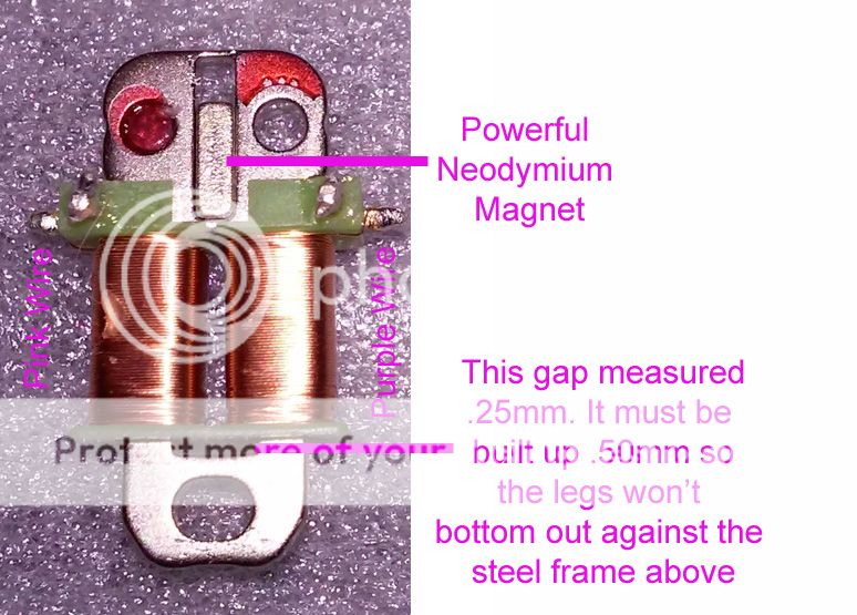
8) Here’s the culprit. The solenoid is shown in it’s activated position, locked in place, even though there is no power applied. When the solenoid is activated, the horse shoe shaped plunger (the bottom piece of steel) is pulled up into the 2 coils, as shown. This activates the arm that controls the aperture opening. The vertical slit in the top of the frame has a powerful neodymium magnet inserted into it. The problem is that the plunger is pulled in so far that the legs of the horse shoe hit the highly magnetized frame at the top of the solenoid. The magnetic pull is so great that the horse shoe plunger is locked in place very solidly. I didn’t think to measure the amount of force to pull the plunger back out, but it has to be at least a couple of pounds. That magnet is surprisingly powerful.


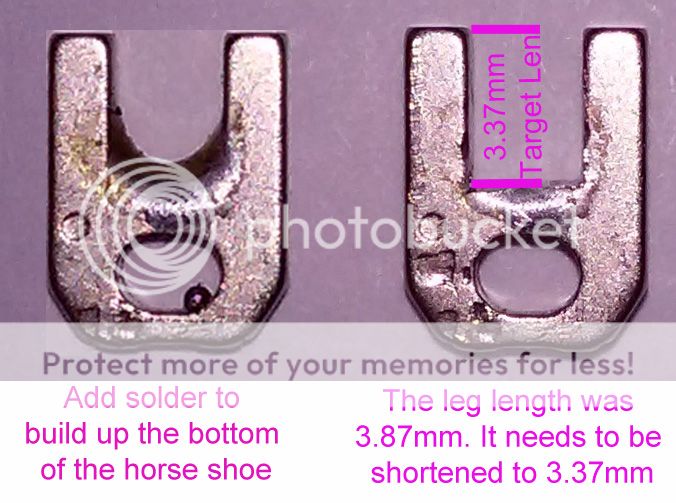
9) Since I didn’t want to make any permanent changes that couldn’t be reversed, I elected to fill in the gap at the bottom of the horse shoe, and then add another .25mm so it would bump the plastic solenoid coil form before the top end of the legs could get magnetically locked to the upper steel frame. So I filled the bottom of the of the horse shoe with solder and then carved it into shape with an x-acto knife (with a new blade) so the legs are now only 3.37mm long, as opposed to the original 3.87mm long.

10) At this point, I put it all back together by just reversing the whole procedure. The camera is taking fine pictures again, and for 0$$. Total time was about 3.5 hours. If you want to try this yourself, here are a few pointers:
Be patient and think things out.
Be gentle - it's a delicate item with even more delicate parts inside.
Have a large, clean and organized work area.
Spread out a clean bath towel over your work area - small parts do not bounce off of a towel.


Last edited by Clover-Leaf; 12-17-2016 at 08:45 PM.
12-17-2016, 09:17 PM - 1 Like   #2
Senior Member
rr1736's Avatar

Join Date: Sep 2011
Location: Chicago Illinois
Photos: Albums
Posts: 203
Wow impressive great work
12-17-2016, 09:25 PM   #3
Otis Memorial Pentaxian
stevebrot's Avatar

Join Date: Mar 2007
Location: Vancouver (USA)
Photos: Gallery | Albums
Posts: 42,007
QuoteOriginally posted by Clover-Leaf Quote
You will need a long small jewelers size Phillips screwdriver to remove the screw that holds it in place.
Welcome to the Pentax Forums and thanks for this comprehensive repair suggestion.

My comment is that the screws are probably not Phillips cross-head. Japanese products made since about 1970 typically use JIS cross-head screws. Phillips screwdrivers will often work, though with some risk of lifting from the head and stripping the slots. A proper JIS screwdriver will be sure.

Edit: How did you arrive at the 3.37mm measurement? Does this affect the "resting" position position of the aperture actuation coupler or change the calibration of actuator? In other words, does a mounted Pentax-A 50/1.2 (the fastest lens native to the mount) open to full aperture and are the body-set apertures the same as those from the aperture ring?


Steve

Last edited by stevebrot; 12-17-2016 at 09:37 PM.
12-17-2016, 09:38 PM   #4
Pentaxian
swanlefitte's Avatar

Join Date: May 2015
Location: Minneapolis
Photos: Gallery
Posts: 4,068
Thanks for taking the time to write that up so clear. Great job and very interesting.

12-17-2016, 10:18 PM   #5
New Member


Join Date: Jan 2013
Location: New England
Posts: 2
Original Poster
QuoteOriginally posted by stevebrot Quote
Welcome to the Pentax Forums and thanks for this comprehensive repair suggestion.

My comment is that the screws are probably not Phillips cross-head. Japanese products made since about 1970 typically use JIS cross-head screws. Phillips screwdrivers will often work, though with some risk of lifting from the head and stripping the slots. A proper JIS screwdriver will be sure.

Edit: How did you arrive at the 3.37mm measurement? Does this affect the "resting" position position of the aperture actuation coupler or change the calibration of actuator? In other words, does a mounted Pentax-A 50/1.2 (the fastest lens native to the mount) open to full aperture and are the body-set apertures the same as those from the aperture ring?


Steve
Thanks for the info on the Japanese screw drivers. I has no idea. The screw drivers I had did fit solidly, but I think you are quite right on the JIS drivers.

I came up with the 3.37 measurement as follows: The legs of the horse shoe plunger contact the the upper solenoid frame, which magnetically locks the legs in the actuated position. In order to keep a gap between the legs and the upper frame, I elected to limit the travel of the plunger, so that the legs and the frame would have a gap when the solenoid was actuated. The legs originally measured 3.87 mm long. The gap between the solenoid coils and the lowest part of the plunger gap (at the center) was .25mm. In order to keep a gap between the upper part of the plunger legs and the magnetic frame above, I picked another .25mm. Any closer and the legs would get magnetically locked in place again.

I don't believe this will affect the aperture opening. From what I understand the aperture setting is in a separate mechanism. The solenoid is there to lock the aperture setting in place. Hope this helps....
12-17-2016, 10:52 PM   #6
Otis Memorial Pentaxian
stevebrot's Avatar

Join Date: Mar 2007
Location: Vancouver (USA)
Photos: Gallery | Albums
Posts: 42,007
QuoteOriginally posted by Clover-Leaf Quote
I don't believe this will affect the aperture opening. From what I understand the aperture setting is in a separate mechanism. The solenoid is there to lock the aperture setting in place. Hope this helps....
Cool

I have never seen the mechanism in motion, just still photos and textual descriptions. If the solenoid acts as a mechanical gate/relay, that is one thing; but if its motion is proportional based on coil voltage, there could be a problem. Recent higher-end models use a separate stepping motor for aperture actuation and it has not been clear to me whether the consumer-line models used a mechanical stepping mechanism or some sort of gearing to manage the movement of the coupler.


Steve
12-17-2016, 11:25 PM   #7
Moderator
Not a Number's Avatar

Join Date: Mar 2012
Location: Venice, CA
Posts: 10,526
I'm trying to wrap my head around how this thing works and what is failing.

A traditional solenoid works by applying current to the coil which creates a magnetic field that draws the plunger into the coil. The plunger is released by stopping the current and is withdrawn mechanically either by a spring or another coil or solenoid.

This device appears to use a permanent magnet to draw the plunger into the coil and the magnetic field of the coil neutralizes that of the magnet allowing the plunger to be withdrawn.

Ok, so what keeps the plunger from being drawn in? How is the plunger withdrawn? Via a spring or some other means like a motor or solenoid?

What fails? Does the plunger get magnetized to the point the coil cannot neutralize the magnetic attraction between the magnet and the plunger? Does the plunger or coil wear so that the plunger travels too far and the coil can't overcome the forces? Does the power circuit fails so that it doesn't supply enough current to the coil to overcome the magnetic forces? Does the mechanism that withdraws the plunger fail? Is the insulation (varnish) on the coils failing so shorts are forming so not enough magnetic force is being generated? Is the magnet out of specification and just too powerful? Is the "latching" mechanism that keeps the plunger from being drawn in failing?

Other related solutions that have been tried (and seem to work):

Sanding the tips of the plunger to make the rounder and reducing the surface area of contact
Making the plunger longer or less magnetically attractive by adding solder to the tips.

12-18-2016, 02:46 AM   #8
Veteran Member


Join Date: Jun 2015
Location: South West UK
Photos: Albums
Posts: 1,493
Yes, it would be nice to understand the whole mechanism... My guess would be that, in order to make the motion snappy, the return spring is strong..and then in order to reduce the overall size and weight of the solenoid needed to counter the spring, a 'helper' magnet is supplementing its force. Possibly the root cause (if that is the case) would be the spring relaxing such that it cannot counter the permanent magnet any more.

I would doubt that the armature has worn by that amount, especially given the low shutter count of a lot of these bodies. So as much as this might be a perfectly valid hack, I'm not convinced it is fixing the actual issue.
12-18-2016, 03:02 AM   #9
Digitiser of Film
Loyal Site Supporter
BigMackCam's Avatar

Join Date: Mar 2010
Location: North East of England
Posts: 20,703
QuoteOriginally posted by Not a Number Quote
Other related solutions that have been tried (and seem to work):

Sanding the tips of the plunger to make the rounder and reducing the surface area of contact
Making the plunger longer or less magnetically attractive by adding solder to the tips.
Whilst the OP's solution is clever and seems to do the trick, sanding the tips of the plunger would seem to be a slightly better approach (no disrespect to the OP). That way, when the solenoid is activated, the position of that oval hole that the pin sticks through would be exactly the same.
12-18-2016, 08:39 AM   #10
Loyal Site Supporter
UncleVanya's Avatar

Join Date: Jul 2014
Photos: Gallery | Albums
Posts: 28,467
QuoteOriginally posted by BigMackCam Quote
Whilst the OP's solution is clever and seems to do the trick, sanding the tips of the plunger would seem to be a slightly better approach (no disrespect to the OP). That way, when the solenoid is activated, the position of that oval hole that the pin sticks through would be exactly the same.
Clearly not a reversible solution however. I think when experimenting using a reversible option is very sensible.
12-18-2016, 08:53 AM   #11
Digitiser of Film
Loyal Site Supporter
BigMackCam's Avatar

Join Date: Mar 2010
Location: North East of England
Posts: 20,703
QuoteOriginally posted by UncleVanya Quote
Clearly not a reversible solution however. I think when experimenting using a reversible option is very sensible.
Yes, I agree... Once you've filed away original material, there's no easy way of putting it back!
12-18-2016, 10:49 AM   #12
Senior Member
GolNat's Avatar

Join Date: Sep 2016
Location: USA-Delaware
Posts: 134
QuoteOriginally posted by Not a Number Quote
I'm trying to wrap my head around how this thing works and what is failing.

A traditional solenoid works by applying current to the coil which creates a magnetic field that draws the plunger into the coil. The plunger is released by stopping the current and is withdrawn mechanically either by a spring or another coil or solenoid.

This device appears to use a permanent magnet to draw the plunger into the coil and the magnetic field of the coil neutralizes that of the magnet allowing the plunger to be withdrawn.

Ok, so what keeps the plunger from being drawn in? How is the plunger withdrawn? Via a spring or some other means like a motor or solenoid?

What fails? Does the plunger get magnetized to the point the coil cannot neutralize the magnetic attraction between the magnet and the plunger? Does the plunger or coil wear so that the plunger travels too far and the coil can't overcome the forces? Does the power circuit fails so that it doesn't supply enough current to the coil to overcome the magnetic forces? Does the mechanism that withdraws the plunger fail? Is the insulation (varnish) on the coils failing so shorts are forming so not enough magnetic force is being generated? Is the magnet out of specification and just too powerful? Is the "latching" mechanism that keeps the plunger from being drawn in failing?

Other related solutions that have been tried (and seem to work):

Sanding the tips of the plunger to make the rounder and reducing the surface area of contact
Making the plunger longer or less magnetically attractive by adding solder to the tips.
Maybe instead of a return spring the magnet is used to return the plunger. The coil always seems to be "closed" (small aperture). Current is applied to the coil to increase the aperture to the needed amount and then the magnet returns the plunger to the "closed" state.

Seems like the tolerance is to close and it gets stuck and the coil is not strong enough to over come this. Possibly due to a weak battery and not enough energy to overcome the magnet.

Great write up by the way Clover-Leaf. If my K-50 ever developed the issue I was going to tear into it also and see what I could find, saves me the trouble.
12-20-2016, 05:21 AM   #13
Pentaxian
amrocha's Avatar

Join Date: May 2010
Location: Catalao GO Brasil
Photos: Gallery
Posts: 326
Very nice and detailed post, thanks for sharing. Is the 3.37mm soldering solution the same one as the original Russian you mentioned, or did you come up with it?
I have a K-x with the aperture control problem. I am wondering if this would work with it. Does anyone there have any idea about it?
12-20-2016, 05:38 AM   #14
Moderator
Not a Number's Avatar

Join Date: Mar 2012
Location: Venice, CA
Posts: 10,526
QuoteOriginally posted by amrocha Quote
Very nice and detailed post, thanks for sharing. Is the 3.37mm soldering solution the same one as the original Russian you mentioned, or did you come up with it?
I have a K-x with the aperture control problem. I am wondering if this would work with it. Does anyone there have any idea about it?
As I recall from the lengthy thread on the Russian fix the solution was to sand or polish the U shaped piece. However it was not clear which areas and how much to sand/polish. Results varied.

https://www.pentaxforums.com/forums/151-pentax-k-30-k-50/321871-k-30-k-50-ape...available.html
12-20-2016, 06:09 AM   #15
Senior Member
Nuno Almeida's Avatar

Join Date: Sep 2014
Location: Aveiro
Posts: 179
Great Job . My old K-50 developed the problem after being stored for some time, I can still get it back to life, but it happens every time when I start it, gone try your approach, but will try to shorten the legs, maybe round them on the tips a bit to decrease surface area, the k-50 is backup at them moment barely rarely use it after I bought the K-1 .
Reply

Bookmarks
  • Submit Thread to Facebook Facebook
  • Submit Thread to Twitter Twitter
  • Submit Thread to Digg Digg
Tags - Make this thread easier to find by adding keywords to it!
aperture, board, bottom, camera, force, frame, horse, k-30, k-50, magnet, pentax k30, pentax k50, photo, post, replacement, rick, screw, screws, shoe, solenoid, teflon, time, wires

Similar Threads
Thread Thread Starter Forum Replies Last Post
K-30 / K-50 Aperture Block Failue - Repair Solution available Altglas Pentax K-30 & K-50 1050 12-03-2023 12:25 AM
K-30 Aperture control and battery problem mgvh Troubleshooting and Beginner Help 10 10-21-2016 06:56 AM
K-30/ K-50 Aperture DIY Repair richandfleur Repairs and Warranty Service 25 07-30-2016 03:13 PM
K-30 Aperture lever - Convert to IR, fix it , flog it, or bin it? Ian.morgan Repairs and Warranty Service 17 05-02-2016 09:27 AM


All times are GMT -7. The time now is 11:29 AM. | See also: NikonForums.com, CanonForums.com part of our network of photo forums!
  • Red (Default)
  • Green
  • Gray
  • Dark
  • Dark Yellow
  • Dark Blue
  • Old Red
  • Old Green
  • Old Gray
  • Dial-Up Style
Hello! It's great to see you back on the forum! Have you considered joining the community?
register
Creating a FREE ACCOUNT takes under a minute, removes ads, and lets you post! [Dismiss]
Top