For:
K3/K3II, K5, K5II, K5IIs, K7
The E-Dials of the professional Pentax bodies are different to those in the entry cameras.
I haven't checked yet on the K30/50/500 nor K-S1/K-S2/K-70 but those will either be similar as you can read in
THIS TUTORIAL or similar to the K5/7/3 etc.
Disassembling is very easy because only the TOP needs to come off!
Best to make some simple drawings and glue those onto a piece of cardboard. Markings where the screws are located, pinch 2mm holes and then stick the screws inside there.
Tools:
-
JIS 00 or 000 screwdriver: I use the
Vessel 9902-set because I like the length which is usefull for the solenoid repairs as well as for the screw inside the battery-chamber. I don't like the Vessel T-Series very much, too flimsy and not strong enough.
But a PH00 will do as well!
-
DeoxIT FaderLube: But
no contact cleaner. Avoid like hell!
- very small flat-blade screwdriver if you want to clean the ISO and EV buttons as well (which is sensible)
Warning: Although the contacts of the flash-condensor are well hidden behind the front-cover and thus there is not the usual shock-hazard as when the body is completly disassembled: Do not poke around in the flash-region itself, neither swallow the Li-Ion battery nor any other parts, because this might lead to
different hazards which you definitely want to avoid!
1. Two screws behind the rubber eyecup:  2. Open pop-up-flash: Two screws there:
  3. One screw deep inside the battery-chamber:
  4. Two screws right side (grip):
 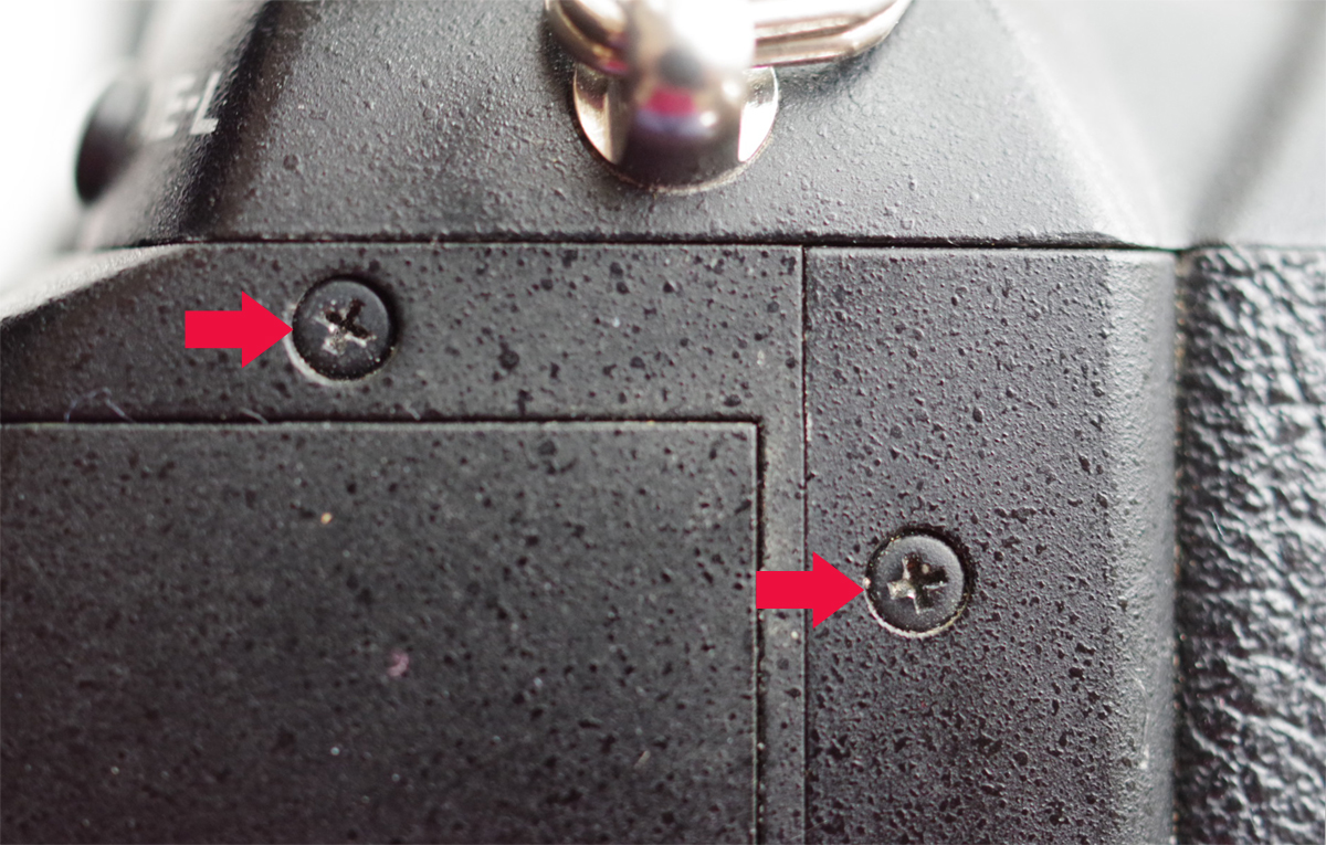 5. Three screws left side
 (one is hidden underneath the rubber =
green arrow):

Here the hidden one again (
left red arrow):

You don't need to unscrew the one right behind the X-Sync-Socket (
blue arrow)! Only necessary if you want to take the front off!)
Now you can lift the TOP of your Pentax but be carefull, there are wires and flat-ribbon-cables!
Carefully place it on the left side without bending/hurting the cables/wires! Not difficult, just some care needed.
6. Three screws for the Top-LCD:  7. Two screws for the "Back-E-Dial":
  8. Two screws for the "Front-E-Dial":
  9. One screw at the back of this E-Dial:
 10. The E-Dial itself:
- Spray a tiny amound of "DeoxIT FaderLube" onto this tiny potentiometer which sits on the green board.
- Clean the leftovers right away ioff and mount it back onto the wheel with the 2 screws, turn the wheel several times into both directions!
- Same procedure for the front-E-Dial (I would always do both, even if it is just one not working alright!)
11. As you are already that far and the top-cover is lose, you now can clean the EV- and ISO-Buttons as well,
remove the three screws and clean them just with some isopropyl-alcohol or similar:

Each button is fixed with a tiny retaining ring (radial e-clip). You just losen it with a tiny flat-blade screwdriver and make sure, it doesn't jump off! So this white blanket under the camera is a good idea.
Of course it makes sense to clean the
ON/OFF-SWITCH at the same time at the same time with
isopropyl-alcohol as well:
Use a
cotton-swab and rub the lower-part carefully, another cotton-swap for those 3 fingers with 2 contact-points on each but only from the back to the front, so that you avoid bending them! They are a bit sensitive and must stay exactly in their position! Not that one bends them easely but they are made out of gold-plated beryllium-copper (spring-copper) which is strong and durable but I have seen some bent ones, then they need to be replaced. So just some care is needed.
Re-assemble everything
and enjoy how smooth the E-Dials work again!
Last edited by photogem; 07-15-2021 at 01:06 AM.


 The difference is marginal and of zero importance for the practical person taking on the job.
 )
)


 Post #1 by photogem
 Similar Threads


