Forgot Password
Pentax Camera Forums Home
 

Reply
Show Printable Version 1 Like Search this Thread
04-28-2014, 03:17 AM   #16
Senior Member


Join Date: Jul 2013
Location: Melbourne
Photos: Albums
Posts: 273
Original Poster
QuoteOriginally posted by RobA_Oz Quote
It would make an excellent engineering student design problem. The radial and angular locations of the body drive and lens coupling axes are the important parameters, and then it becomes a matter of which type of drive is best. Pinions and ring-gears are the likely candidates, with the challenge there being the ring-gear locating method. Space shouldn't be a big issue with that system.


Personally, I would love to attempt building and designing something like this, but in order to do so, I would need to have stuff to play around with, which unfortunately costs money

04-28-2014, 03:22 AM   #17
Senior Member
delegopa's Avatar

Join Date: Apr 2013
Posts: 244
The mechanical Power of the motor is 2*pi*Torque(rpm)*rpm The electric Power is usually only given for the nominal speed and is larger than the mechanical output power.
This means the output Power is dependent on the rpm and not constant(mostly). You need the Torque at halt to verify if it works with 645 lenses. This can be found in the datasheet. The characteristic curve Torque over rpm can look very different depending on the kind of motor and the way it is electrically connected. But such data will be hard to come by... The required Torque for the lens gear is usually unknown too.

Got some DC motors flying around here, mainly from old printers. Its harder to work with them when I cant find the datasheet. You can rip your K3 open to see the motor label, but this does not guarantee you will find the data or at least can get it back together... So dont do it

If the 645 lenses actually can be focussed with the motor, there could be problems with heat and faster detoriation because of the higher required torque. Hower it could acually work but I would rather do this on an old body.
04-28-2014, 03:37 AM   #18
Senior Member


Join Date: Jul 2013
Location: Melbourne
Photos: Albums
Posts: 273
Original Poster
QuoteOriginally posted by delegopa Quote
The mechanical Power of the motor is 2*pi*Torque(rpm)*rpm The electric Power is usually only given for the nominal speed and is larger than the mechanical output power.
This means the output Power is dependent on the rpm and not constant(mostly). You need the Torque at halt to verify if it works with 645 lenses. This can be found in the datasheet. The characteristic curve Torque over rpm can look very different depending on the kind of motor and the way it is electrically connected. But such data will be hard to come by... The required Torque for the lens gear is usually unknown too.

Got some DC motors flying around here, mainly from old printers. Its harder to work with them when I cant find the datasheet. You can rip your K3 open to see the motor label, but this does not guarantee you will find the data or at least can get it back together... So dont do it

If the 645 lenses actually can be focussed with the motor, there could be problems with heat and faster detoriation because of the higher required torque. Hower it could acually work but I would rather do this on an old body.


Honestly, if I were going to play around with this I would probably start with a used K7 and work my way up the hierarchy, so that I don't break a $1200 brand new camera
04-28-2014, 03:42 AM   #19
Senior Member
delegopa's Avatar

Join Date: Apr 2013
Posts: 244
QuoteOriginally posted by carrrlangas Quote
Adam is probably right, the motor must be the same between K-7 and 645D sd they were developed at the same time (same AF system, processor, screen, probably same af motor). But even if the 645D motor was more powerfull you could still use the K-3 motor with the proper combination of gears, resulting in a slower speed to get the necessary torque.
This is actually a good idea as you will just need to short circuit 2 contacts to get the AF system running on the body. The diffcult part will be finding the space to place the gears between body and lens mount.

EDIT: Actually, there seems to be some space available:
That is a good suggestion. A gear reducer would be a good way to get this working without greater knowledge of the motor power.

About the dc motors in the lenses: Would be really interesting to see their construction. But i dont think it will be a stepper motor. To properly drive those the camera would need to know a lot more about the lens. For bipolar steppers it would need 4 pins to power it. You dont need to count steps, because with the AF sensors you actually get some kind of servo motor with any motor.

04-28-2014, 03:47 AM   #20
Senior Member


Join Date: Jul 2013
Location: Melbourne
Photos: Albums
Posts: 273
Original Poster
So, not that id do it, but do guys think a AF adapter would sell here on PF forums?
04-28-2014, 03:50 AM   #21
Site Supporter
Site Supporter
RobA_Oz's Avatar

Join Date: Nov 2008
Location: Tasmania, Australia
Photos: Gallery
Posts: 8,209
QuoteOriginally posted by delegopa Quote
That is a good suggestion. A gear reducer would be a good way to get this working without greater knowledge of the motor power.

About the dc motors in the lenses: Would be really interesting to see their construction. But i dont think it will be a stepper motor. To properly drive those the camera would need to know a lot more about the lens. For bipolar steppers it would need 4 pins to power it. You dont need to count steps, because with the AF sensors you actually get some kind of servo motor with any motor.
The whole point about the piezo-electric and other stepper drives is that you can easily count pulses, which gives you control of how far you move the load (in this case, a lens or group). Then you just need a rotary or linear encoder at the output end to give you absolute position feedback. Slippage occurs in all drive systems where friction is involved, which gives DC steppers an advantage over piezo drives.
04-28-2014, 03:57 AM   #22
Veteran Member
carrrlangas's Avatar

Join Date: Mar 2012
Location: Joensuu (Finland)
Photos: Gallery
Posts: 1,761
QuoteOriginally posted by RobA_Oz Quote
The whole point about the piezo-electric and other stepper drives is that you can easily count pulses, which gives you control of how far you move the load (in this case, a lens or group). Then you just need a rotary or linear encoder at the output end to give you absolute position feedback. Slippage occurs in all drive systems where friction is involved, which gives DC steppers an advantage over piezo drives.
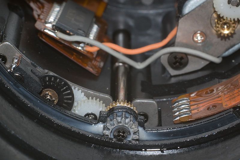
I think they donīt use stepper motors as lenses include some way of calculating how much the gears have turned, ie. focus throw. Look at this picture where you can see a sensor at the left with the black plastic gear:


source: https://www.pentaxforums.com/forums/10-pentax-slr-lens-discussion/95105-my-fa...ont-focus.html

04-28-2014, 04:12 AM   #23
Senior Member
delegopa's Avatar

Join Date: Apr 2013
Posts: 244
QuoteOriginally posted by RobA_Oz Quote
The whole point about the piezo-electric and other stepper drives is that you can easily count pulses, which gives you control of how far you move the load (in this case, a lens or group). Then you just need a rotary or linear encoder at the output end to give you absolute position feedback. Slippage occurs in all drive systems where friction is involved, which gives DC steppers an advantage over piezo drives.
But steppers have step loss Made up my mind on some thoughts I already posted: The camera mainly provides the power and commands. The hard- and software for motor control is all in the lens. So a stepper would be possible. But I still think it will be something else. When you have absolute position feedback as you said you dont need steps. Both encoders and steppers are "pricey" options. A stepper in camera would make more sense to me.

"I wonder whats actually in there. Why do you look so scared now, MZ-50? Come back here! I want to see your insides...
No, calm down, you are safe, 18-135. As long as you are still working..."

---------- Post added 28-04-14 at 04:22 ----------

QuoteOriginally posted by carrrlangas Quote
I think they donīt use stepper motors as lenses include some way of calculating how much the gears have turned, ie. focus throw. Look at this picture where you can see a sensor at the left with the black plastic gear:


source: https://www.pentaxforums.com/forums/10-pentax-slr-lens-discussion/95105-my-fa...ont-focus.html
Thats an interesting contribution. Looks like it is a basic incremental concept then. When you start up your camera the AF wont do anything (without user commands). Thus it does not look for an end stop. Therefore it could be possible that the lens never knows its actual position and only counts the turns made. Did you see any other sensors for the AF system when you opened your lens? So far I only looked into fully mechanic lenses.

Last edited by delegopa; 04-28-2014 at 04:23 AM.
08-19-2014, 02:19 PM   #24
Senior Member


Join Date: Jul 2013
Location: Melbourne
Photos: Albums
Posts: 273
Original Poster
So, obviously this is quite an old topic, but I've decided that once I'm off my holiday, I will actually attempt to build a 645 to K-Mount adapter. Like any non factory standard product, there will be limitations and restrictions, such as I'm only going to armor with the older FA screwdriver lenses and not newer SDM or DC lenses, and I'm going to cheat the electronicics out of the equation, and instead fool the camera to believing that there is an A setting available, when there's is not and the camera is simply working in Av or M mode.

I'm assuming that k mount cameras need a focal length inorder to utilize phase detection and contrast detection autofocus, so the concept adapter will be tailored to one lens only. So now I just need to design it in CAD and figure out the gearing.
Reply

Bookmarks
  • Submit Thread to Facebook Facebook
  • Submit Thread to Twitter Twitter
  • Submit Thread to Digg Digg
Tags - Make this thread easier to find by adding keywords to it!
645d, af, body, camera, contacts, control, dc, design, drives, dslr, feedback, gears, k3, lens, lenses, motor, motors, photography, position, power, power of k3, space

Similar Threads
Thread Thread Starter Forum Replies Last Post
How to power an LX motor drive w/o battery pack? innivus Film SLRs and Compact Film Cameras 3 02-27-2014 07:39 PM
replacement motor of a locked up mirror zimmicha Visitors' Center 5 02-11-2014 10:15 PM
So does K3 actually have a brushless motor? horc00 Pentax K-3 & K-3 II 6 12-24-2013 05:17 AM
Autofocus comparison : lens motor vs. body motor (screw drive) 6BQ5 Pentax K-30 & K-50 7 06-12-2013 12:12 PM
K20D defaulting to screwdrive focus instead of SDM shemj Pentax DSLR Discussion 15 01-26-2010 04:22 PM


All times are GMT -7. The time now is 09:14 PM. | See also: NikonForums.com, CanonForums.com part of our network of photo forums!
  • Red (Default)
  • Green
  • Gray
  • Dark
  • Dark Yellow
  • Dark Blue
  • Old Red
  • Old Green
  • Old Gray
  • Dial-Up Style
Hello! It's great to see you back on the forum! Have you considered joining the community?
register
Creating a FREE ACCOUNT takes under a minute, removes ads, and lets you post! [Dismiss]
Top