Manual: Solenoid Replacment Pentax K-30/50/500 + Discharge of flash-condenser 06-13-2019, 07:25 PM
Solenoid replacement: Pentax K-30 K-50 + K-500 Tools:
- Soldering iron with pencil-tip: Ersa Multi-Pro 20W or soldering needle/USB soldering iron.
... I use the Weller WS81® soldering-station.
... (Butan-gas soldering-iron = An absolute No-Go! Too hot, it will do damage!)
- Solder: Good quality thin resin flux solder
... I use 0,75mm S-SN60PH40 leaded-solder which melts already at 190° C:
... For such short and small work it is not really dangerous because it contains some lead.
... You can also use rosin-/fluxfree solder and add colophonium later on, my personal prefered method.
- 1 x Screwdriver JIS 000 or JIS 00 (you can also use a PH00 + PH000 but JIS is better, Pentax screws are JIS!)
- 1x tiny Screwdriver flathead like 1.8mm (for lifting the rubber-grips held by double-sided-tape)
... The Vessel 9902 set is ideal, the long JIS screwdriver is perfect for reaching the screw of the solenoid!
- 1x Tweezers or precision pliers
- Headlamp is useful!
- Photos of all sides of K30/50/500
- And of course the correct solenoid, i.e. the whiteJapan-DSLR-Version ONLY! Don't let yourself be fooled by wrong solenoids!
Why only this one you can study HERE
(and we don't discuss other solenoids in this tutorial as this not for cheapskates but the only proper solution!) Preparation:
Print out the photos with the location of the screws, glue them on cardboard and drill 1.5 - 2mm holes where the screws are located. Thus you can place all of the screws into those holes because they are of different length: 
Magnetize the tip of your screwdriver (there is no danger to the camera!) so the screws "stick"to the tip of the screwdriver. Make sure the body-cap covers the opening of the lens-mount for protection of the sensor etc.!
Take the battery out and open the pop-up flash.
Attention: Be careful that you don't charge the flash-condenser, you should anyway discharge it later on (or at least don't touch it) This black condenser is situated left to the AF/C/M- switch. The Plus (+) contact is to the front, minus (-)sits behind. The danger isn't in touching the Plus-contact but in touching the circuit-board above:
On the photo you see the blue wire which carries the high voltage of the flash-condenser!

Discharge of the flash-condenser:
Best done with an old fashioned wolfram-filament ca. 60W light-bulb (or a 1 - 1,6 k ohms/10W resistor). A Light-bulb is better because you see the discharge! Solder some insulated wires directly onto the light bulb or on a lamp-socket and insulate any contacts! Have the other ends of the wires 0.5 cm bare (soldered). With one of those wire-ends you touch the metal K-bayonet (which is minus) and with the other end, you touch the front contact ofthe flash-condenser (Remember, this goes for the K30/50/500! For other Pentax DSLR make sure you identify which contacts are plus and minus!) The light bulb will illuminate until the condenser is discharged. The other option is to remove the battery and leave the camera without it for at least 48 hours. The condenser will discharge within that time. The photo shows how I discharge the condenser: I use measuring cables because I do it more often. 
Sequence of opening the body: (Body-cap on the body!)
1. Remove all screws from the bottom part. Do not forget the long silver screw inside of the battery compartment! When the bottom-part is off, you can see one small screw next to the grey battery holder, it belongs to the frontpart. Take that one off as well and make sure you dont forget this one later!

2. Remove all screws from the frontpart: (The small one on the bottom is already out!)
There are 3 screws on the left side (2 of them hidden underneath the rubber, you lift the rubber with the tiny flathead screwdriver, it is held with double-sided tape): This rubber you can remove completly):

Then there are 2 screws on the right (grip-) side, the upper one hidden as well, you just have to partly lift the rubber here (flathead screwdriver) for access of this screw: 
3. Take all screws of the top part: 1 screw on each side where you fix the strap and 3 screws unterneath the pop-up-flash (which you opened without battery, remember!).
The K50/500 has only 2 screws here)

And then 2 screws on the backside behind the rubber-eyepiece: 
You have to lift the top part slightly so it doesn't hold the front-part anymore. But don't lift it off completely! This lifting of about 1 cm is important because otherwise you will find it more difficult assembling the front part back into its position and adjusting the external part of the AF-S-C-M-switch to its internal counterpart!
Also you have much better access to the left pink wire on the solenoid. If you would lift the top part off completely you have to be very careful, there are critical wires and one flat ribbon wire which can easily get damaged.
4. Take the front-part off.
Have the AF-switch on position AF-S = upwards
but ..the inner counterpart opposite = downwards
Check this again before you later place the front part back into its position!
In almost every K-30/50 etc. repaired by myself I found that this inner part moves.
So this is crucial!
In AF-S position the screw-drive-mechanism pushes through that tiny hole in the bayonet to drive the AF of the lens! In C-position as well.
In M-position it moves back, so the lens is in manual position. Best to move the AF switch a few times to understand its function!
The AF-S-C/M-switch in AF-S-position: 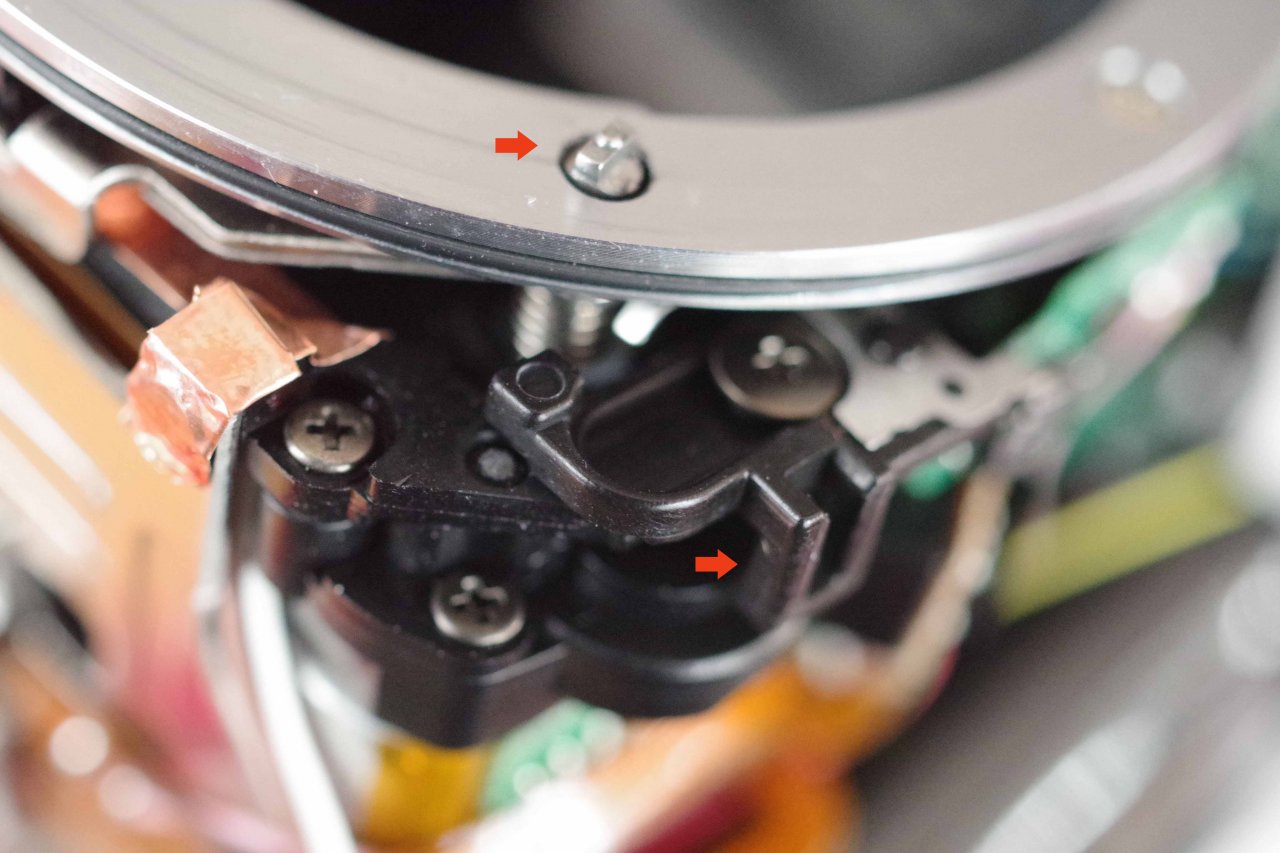 You can clearly see, the screwdrive-mechanism extents out of the small hole! You can clearly see, the screwdrive-mechanism extents out of the small hole!
Here the inner side of the external part of the AF-S C/M-switch:: The metal rod has to fit exactly onto the inner part of the switch! If you follow the steps as explained nothing to worry about!
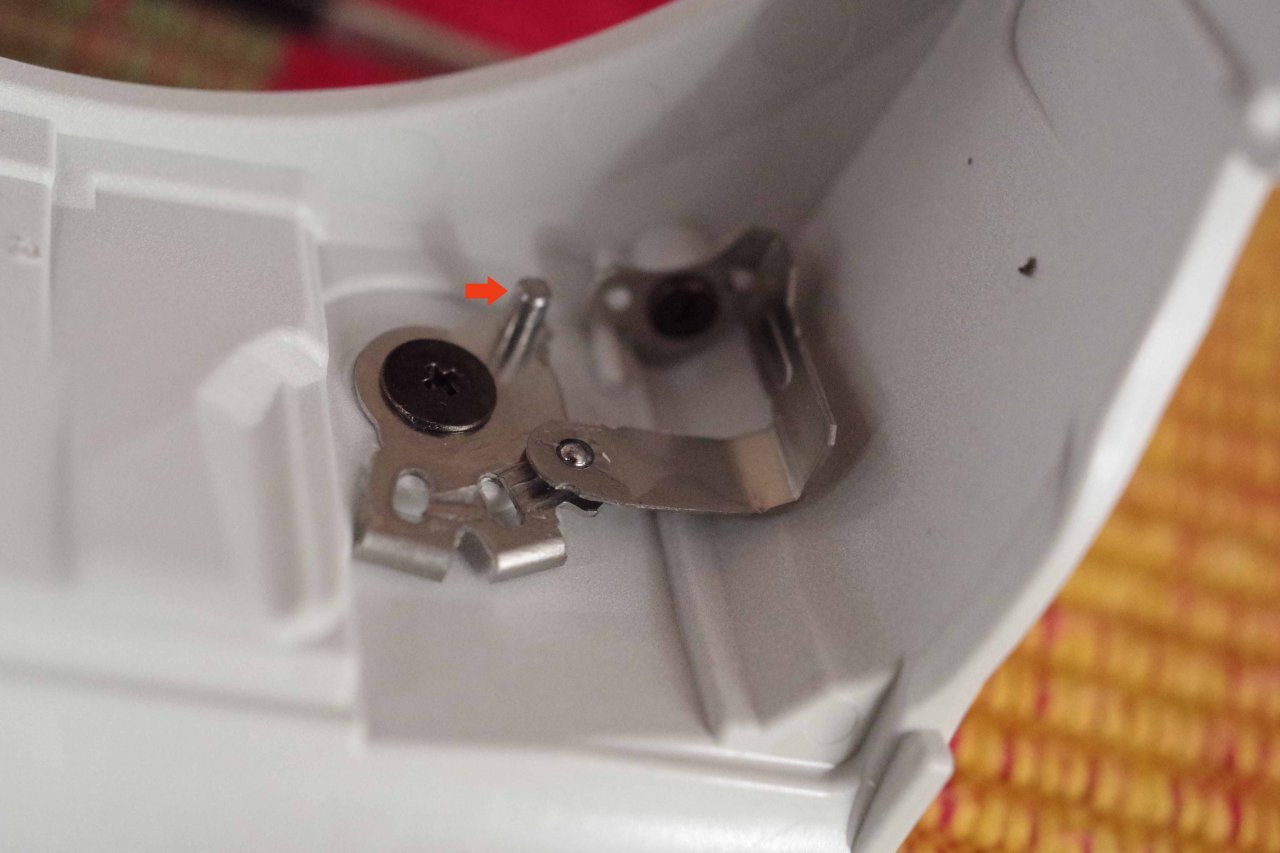 below this rod you can see also this tiny ball which stops in those 3 different positions AF/C/M. below this rod you can see also this tiny ball which stops in those 3 different positions AF/C/M.
Make sure you don't lose it (it sits there pretty well jammed, so very unlikely to go lose)
Exchange of Solenoid:
Place the body on a soft tissue with the LCD-display downwards, the side of the grip facing towards yourself. Now you have a good view on to the solenoid itself
(Here a headlamp is quite useful!).

a) Unsolder the two wires (pink and lilac) off the solenoid. With the pliers, you hold the wire, then a short contact with the tip of the hot soldering iron. Not too long because you don't want to melt the PET plastic of the green solenoid nor later the PTFE of the white solenoid!
b) Unscrew the solenoid. The solenoid is fixed with a tiny screw on the right, left to it it sits on a plastic mandrel. It is fixed as well with red thread-locking-lacquer. On the bottom you can see the plunger which sits on the metal lever.
- With a very small flat screwdriver, you go behind the metal top part of the solenoid to get it loose.
- Then you grap it with tweezers on the top metal-body and tilt it forward and take the plunger off the lever it sits on.
- Don't touch the 2 coils, the copperwire is sensitive! You've got the green gremlin out. You can see very clearly one of the reasons it works bad: The two coils are not parallel but the plunger has to move within those 2 coils: 
c) Now place a tiny amount of solder onto the ends of those two (pink and lilac) wires which have to be soldered back onto the pins of the new solenoid.
d) Built in the white solenoid. Place it first with the plunger onto the lever (green arrow) and make sure the solenoid sits on this plastic mandrel (small red arrow): 
e) Carefully insert the tiny screw and tighten it: 
You can add some thread-locking-lacquer as well or just use some nail-varnish. Solder the wires back on.
- Make sure each time you solder, you clean the tip of our soldering-iron first, you don't want to bring burned carbon residue into the melted solder.
- Make sure as well, that the solder really melts, don't just "glue" it, solder it! Solder has to "flow"!
- Make sure that the wires and particular the left pink wire are soldered onto the pins from the left side and not from the front. There is very little space for the wires as soon as the top-part is placed back on its place:

- Then check that the wires are tight. For this you hold the wire with tweezers and pull gently. It must hold well! (If necessary google how to solder)
- Now bring first the front-part back into position! Make sure you have the external part of the AF-S/M-switch on AF-S and the inner counterpart downwards so the screwdrive-mechanism is extended.
- Only then* push the top part of the camera back into its position and fix it with 2 of its screws!
*If you would start with the top-part as many show on their videos, you have to jam the frontpart in with the risk of badly squeezing the wires! You want to avoid this!
Function-Test: Close the flash! Put the battery into the battery-compartment, plug an AF lens onto the body, switch your Pentax on and take some pictures with a low aperture value (such as f2, 2,8, 3,5 or even lower depending on your lens). You can see the solenoid in action each time you take a photo.
Check again that the AF-S-C-M switch works!
(If not, the alignement wasn't done proberly, easy to fix now, you don't want to find out a bad alignment after you assembled the complete body!
Take the lens off, battery out and then open the pop-up flash again so you can screw the 3 (2 for the K50/500) screws there back in and continue with all the other screws. Don't forget the tiny screw next to the batterylever and the long screw inside the battery-compartment!


If it's the K50/500 you repair, take care as well with the rubberdoor which closes the USB-connector:

 Part II: Part II:
How to chose the right solenoid?
Several approaches have been tried, such as:
1. Exchange of the solenoid with the white colored "made in Japan" solenoid used in early DSLR bodies: The only real solution!
2. Exchange with the green colored "made in China" solenoid to be found cheaply on evilBay:
Not only a Repeating error but worse that even:
3. Sanding/filing the plunger of the existing solenoid not such a good idea
4. Soldering the plunger of the existing solenoid: Very bad idea, the worst!
5. Selecting solenoids from CD/DVD-ROM drives: Very bad idea, usually those are 15ohms and then will kill the powersupply eventually, but if the cheap Lenovo 30ohm versions sold on ebay: worse than the Original version because an even stronger holding-force due to a larger magnet and lacking the essential side pins
6. Selecting solenoids from SLR Pentax bodies: Bad idea
#1. This is after all the only long term satisfying method. All solenoids which were made in Japan have worked for long times and there were no reported issues that one of them ever failed. They were first introduced for the old analog SLR bodies but with small differences in size and holding-force and sometimes opposite polarization. You want those which were used in the earlier Pentax DSLR bodies such as:
*ist D, *ist DS (Samsung GX1), *ist DS2(Samsung GX1s), K100D, K110D, K200D, K-m (2000), K-x, K-r (all those have 2 solenoids built in: One in the aperture circuit, one in the flash circuit).
The made in Japan solenoid was also used in the K10D (Samsung GX10) and K20D(Samsung GX20). High shutter count was achieved with them and never any reported solenoid failure. Those were then the cream-of-the-crop!
The body of the green made in China solenoid is made out of PET. The white made in Japan solenoid uses PTFE (Teflon), a superior and much longer lasting material. The green solenoid was first sometimes applied in the flash compartment of some (not all!) Pentax K100D, K110D, K200D, K-m, K-x and K-r (it seems mostly Europe). The first body with the green solenoid used in the aperture-circuit was the Pentax K30. It was the K30, followed by the K50 and K500 which stirred up users because of pictures almost completely dark i.e. underexposed: The reason was the plunger of the solenoid remaining stuck to the hold of the permanent magnet which sits in the small long sleeve on top of the two coils. Those 2 coils act as an electromagnet, producing an opposing magnetic field to the existing magnetic field of the permanent magnet. When this magnetic field in annulled, the plunger moves out according to the readings of a small sensor reading the applied aperture. There is a defined holding force of the permanent magnet in relation of how much the plunger can be magnetized.
It has been measured, that the holding force of the "green made in China solenoid" is larger than the holding force of the white "made in Japan" solenoid. This is also very easy to just "sense" when one pulls the plunger out of the body of the white solenoid compared with the green solenoid. The difference is pretty obvious. You need much more force for the plunger of the green solenoid.
Here you can see one difference between the older SLR solenoid and the correct early DSLR Japan-Solenoid:
The earlier analog SLR versions release that tiny bit quicker (even less holding force) but also they sit with a minimal tilt when built in into a Pentax DSLR and thus the plunger sits slightly tilted on the aperture-control-mechanism: 
Compared to this 100% accurate straight line of a 'DSLR white made in Japan solenoid': 
I myself and a few others in Europe also came across opposite polarized solenoids in the MZ-Series. This is very easy to check: The left contact (solenoid in K30 aperture mechanism!) pink wire is plus (+),the right contact (lilac) is minus (-). Solder long wires onto the pins, connect them for a short moment to a 3V battery: If the plunger can be pulled out without almost zero resistance: Polarity is correct. If the plunger sits even tighter: Opposite polarization. But even then they can be used but one has either to change the wires in the Pentax or adding length to the pink left wire so it can be soldered to the right side.
I have found correct polarized solenoids on MZ50 and MZ7 "made in Japan", but opposite polarized solenoids in those assembled in Philippines. It seems most MZ-Series Pentax' sold to Europe were assembled in the Philippines. I have not invested further because the solenoid from the early DSLR bodies anyway is the only correct one to use, the MZ solenoids have even less holding-force because they were made for 6Volts from 2x CR2 batteries which don't have much mA and thus the solenoid needs to actuate under different conditions.
This lower holding-force often leads to the opposite of ABF: The plunger stays "open" and all photos are overexposed. Also misalignement of the complex mechanism can happen, similar to the sanded plunger of the green solenoid, in worst cases unrepairable, in good cases expect about 14 hours extra work because deep disassembly is then what you have to take on!
Using the DSLR "made in Japan white solenoid" is the only save way to allow the aperture mechanism not to fail again!
2: Nothing more needs to be said about this method. It would be rather silly to take on all this work of disassembling your K30, 50 etc but then do it worse!
This brings us to
3: Sanding, filing even grinding the plunger. This method promised a cheap and safe way to go. It is applied by some repair-shops, but there have been reported problems! A camera is a precision instrument and the sanding / filing solution introduces more problems than it fixes.
To achieve a similar holding force such as the white made in Japan solenoid guarantees this method changes the movement of the plunger in the already cheaper and easier to be worn out PET body of the green solenoid. A tilted plunger can eventually lead to a complete blockade of the mechanism: See the next photos of how tilted the plunger of the green solenoid sits compared to the straightness of the white made in Japan solenoid:  
The mechanism which the solenoid brings into action is itself quite complicated and demands the solenoid to work very precise:

With sanding the plunger quite often the wheels get stuck or get de-arranged.
The plunger tilts even more:  If a sanded solenoid does more damage, you need to replace the complete socalled diaphragm-control-block : A very complicated undertaking! Changing the solenoid is almost peanuts compared to this work. It takes about 14 hours and one needs to know a lot to take this on! If a sanded solenoid does more damage, you need to replace the complete socalled diaphragm-control-block : A very complicated undertaking! Changing the solenoid is almost peanuts compared to this work. It takes about 14 hours and one needs to know a lot to take this on!
An almost complete disassembly of the camera!
In March 2017 I took those photos to show the difference between the green and white solenoid:   One can clearly see that the plunger of the green solenoid has more "play" to all sides, i.e. it will already move with less guidance. The body with the 2 coils acts as a kind of bearing. The plunger moves in and out of this bearing. With more play there is more danger of tilt which is enhanced when filing/grinding the plunger. One can clearly see that the plunger of the green solenoid has more "play" to all sides, i.e. it will already move with less guidance. The body with the 2 coils acts as a kind of bearing. The plunger moves in and out of this bearing. With more play there is more danger of tilt which is enhanced when filing/grinding the plunger.
Also very clearly visible: Corrosion on the plunger. The material of the green "made in China" solenoid is not of the same quality as the material used with the white solenoid. If there is corrosion where the plunger sits on the lever, there will be as much corrosion on the parts which are filed/sanded!
I came across a many K30/50's with "sanded plungers". And on a few I did notice corrosion when grinding was applied.
4: The method of applying solder to the plunger and file excess solder away is not to be recommended at all. Very bad idea!
The idea itself is similar as in method #3, i.e. to bring the plunger that amount away from the magnetic field of the permanent magnet and thus decrease the holding force. But this will push the plunger further downwards, its position on the aperture control mechanism is then far from ideal and the mechanism is getting strained too much! It will lead to further failure even quicker than the cheap sanding method. I never tried it because logically it made no sense, but I got one K30 for repair and thus had the chance to disassemble it complety. Never again!
There is another method some still suggest: Decreasing the size of the magnet. Well, this is the most stupid thing you can do because the magnet will quickly detoriate! I also tried exchanging magnets: No luck either: Failure. Swapping plungers will not work, nor demagnetising. Don't even think of applying grease, graphite or WD40! Also don't let yourself be fooled into a complete disassembly of your Pentax to access the mechanism deep inside for cleaning parts there. I never ever came across any parts there being dirty, but I came across resulting misalignment.
5: Beware of solenoids from DVD-ROM and CD-ROM Drives! They are either blue or green coloured and are made in China as well. The often have also another impedance (usually 15 ohms) which can lead to damage on the main-board of your Pentax as well as dead coils. The green coloured versions are offered on ebay "en masse" with fake positive reviews. The magnets and therefore the holding-force are stronger, they cannot work! Any claim that they work is based on manipulation, I have tested them from different sources and I have tested 20 of them! If people claim they work without filing/sanding or otherwise manipulating them there are different interests behind.
You can recognize those solenoids easily: The two side-pins are missing, the tiny wires of the coils which normally are soldered onto those side-pins are soldered onto the two upwards-facing pins. Because the green PET plastic has a much lower melting point than the PTFE of the Japan-solenoid, the PET melts very quickly and then you have a loose pin. You don't want that pin all the sudden 'dangling' in your Pentax:

Here a short video showing the solenoid in action
Last edited by photogem; 08-27-2023 at 11:20 PM.
| |


 Post #1 by photogem
 Similar Threads


