| Pentax/Camera Marketplace |
| Pentax Items for Sale |
| Wanted Pentax Items |
| Pentax Deals |
| Deal Finder & Price Alerts |
| Price Watch Forum |
| My Marketplace Activity |
| List a New Item |
| Get seller access! |
| Pentax Stores |
| Pentax Retailer Map |
| Pentax Photos |
| Sample Photo Search |
| Recent Photo Mosaic |
| Today's Photos |
| Free Photo Storage |
| Member Photo Albums |
| User Photo Gallery |
| Exclusive Gallery |
| Photo Community |
| Photo Sharing Forum |
| Critique Forum |
| Official Photo Contests |
| World Pentax Day Gallery |
| World Pentax Day Photo Map |
| Pentax Resources |
| Articles and Tutorials |
| Member-Submitted Articles |
| Recommended Gear |
| Firmware Update Guide |
| Firmware Updates |
| Pentax News |
| Pentax Lens Databases |
| Pentax Lens Reviews |
| Pentax Lens Search |
| Third-Party Lens Reviews |
| Lens Compatibility |
| Pentax Serial Number Database |
| In-Depth Reviews |
| SLR Lens Forum |
| Sample Photo Archive |
| Forum Discussions |
| New Posts |
| Today's Threads |
| Photo Threads |
| Recent Photo Mosaic |
| Recent Updates |
| Today's Photos |
| Quick Searches |
| Unanswered Threads |
| Recently Liked Posts |
| Forum RSS Feed |
| Go to Page... |
PentaxForums.com → Camera Help Central → Pentax Articles → Do-It-Yourself
→
Manual: Solenoid Replacment Pentax K-30/50/500 + Discharge of flash-condenser
 |
| 22 Likes | Search this Thread |
| 11 Likes | #1 | ||
| |||
| Views: 14,808 | |||


photogem | |
 | View full profile |
| Contact via private message | |
| Find other posts by photogem | |
| Find threads started by photogem | |
| Find threads in which photogem has posted | |
| These users Like photogem's post: |

| 06-14-2019, 12:33 AM - 1 Like | #2 |
|
Excellent manual, photogem, even though I probably wouldn't dare this kind of camera surgery myself. Two "follow-up questions" (pretty obvious, really, but just for the record):
| |


| These users Like Madaboutpix's post: |
| 06-14-2019, 07:07 AM | #3 |
|
Thanks. I explained it just recently HERE Ricoh did something about it. It isn't that easy. I have their latest solenoid on my worktable and inspected it, I need a bit more time and will write more about it. It is different but not yet perfect. Basically they cannot have back their white solenoid anymore, I wrote a bit how this happened with Telefunken HERE . This is how it works these days. | |

| 06-14-2019, 08:52 AM - 1 Like | #4 |
|
@photogem, Bravo! Although I do not have any of the affected cameras, I am always thankful to people who document their repairs in such detail and precision. - Craig | |
| These users Like c.a.m's post: |
| 11-27-2019, 11:50 PM - 1 Like | #5 |
|
I have revised the manual and added new photos to make things more clear.
| |
| These users Like photogem's post: |
| 02-22-2020, 09:59 AM - 1 Like | #6 |
|
Successfully followed this outstanding tutorial, replacing my K30 solenoid with a K10 donor one. Soldering was the most tricky part, luckily I had a pencil iron (and some experience from my other hobby: modelrail). The green solenoid taken out didn't seem so asymmetric as the one shown here, perhaps there are/were also quality differences in the green ones? My K30 started having symptoms after six and half years. Thanks again Photogem! Cheers, Gerard | |

| These users Like FotoGekko's post: |
| 02-22-2020, 11:11 AM | #7 |
|
Well done! Asymmetry isn't really the (main) problem. Maybe you compared the holding force, checking about the difference of how much force you needed to pull out the plunger of the green and then the white solenoid? This is the most obvious, almost everybody could tell the difference then right away, it's pretty obvious! The differences, i.e. changes for the better came with the late K50 and all Pentax bodies (with solenoid) after December 2015, you can read here about it: A LITTLE BIT OF HISTORY: Development of the solenoid in Pentax cameras - PentaxForums.com | |
| 02-23-2020, 02:49 AM | #8 |
|
Interesting read that one! Can't compare side to side anymore. Had been hoping to escape with my K30 after some 4-5 years of good service, as most of the fails seemed to occur within 2-3 years, but alas. However, I took over two batteries and a charger locally and the guy told me his K30 failed at 5 years. But good experience this! Cheers, Gerard | |
| 02-25-2020, 11:21 PM - 1 Like | #9 |
|
The failures occur particular often when the camera is not used for a longer time! Another failure as well: If the camera is stored without the battery, the back-up battery (either a rechargeable MS 414 from Seiko or an Elna Supercap) is going to be drained. I guess the ELNA Supercap will last better, the Seiko is Li-Ion and we know too well what happens when they discharge too strongly! | |
| These users Like photogem's post: |
| 04-07-2020, 10:30 AM | #10 |
| Double trouble!!
I acquired a K30 to fix, and then this morning my KS2 displayed block fail symptoms (and I used it only last night to take moon pics  ). ). I feel pretty happy about taking on the fix, I have 2 solenoids from a disassembled K-r, one white one green. Do you think the green solenoid is ok for one of these cameras, or would I be better getting a solenoid out of a film MZ5/MZ50 (immediately available off ebay cheap, no sign of a 1st/K100 etc anywhere). Update just remembered I have a junk pentax A3, does this have the solenoid in? Great job on the write up btw. appreciated. Last edited by marcusBMG; 04-07-2020 at 10:36 AM. | |
| 04-07-2020, 10:48 AM | #11 |
|
The white solenoid of your K-r is perfect. The green one in the flash-mechanism is useless, it is the same one you've got in your K-S2 and K-30, so by all means no. The solenoid in the MZ5 will not fit at all, it is completly different. I don't recommend those from other MZ's, I have explained it in my tutorial, not worth the risk. If you wish to do it well, find another DLSR white Japan solenoid. Plenty of Pentax *ist starting from the D, Samsung GX1/10/20, Pentax K10/20/100/110/200/Km/Kx/Kr Bit of patience and with most of them you have 2 perfect solenoids. | |
| 04-07-2020, 12:09 PM | #12 |
|
I'm sure you're right photogem KS2 is working again (but probably on borrowed time, if this has occurred once then its going to happen again), I'll go ahead and do the K30 for the moment. | |
| 04-09-2020, 12:19 PM | #13 |
|
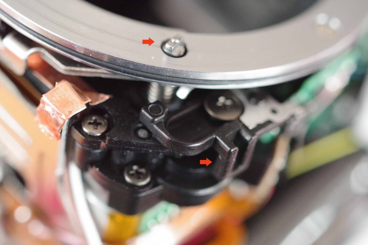
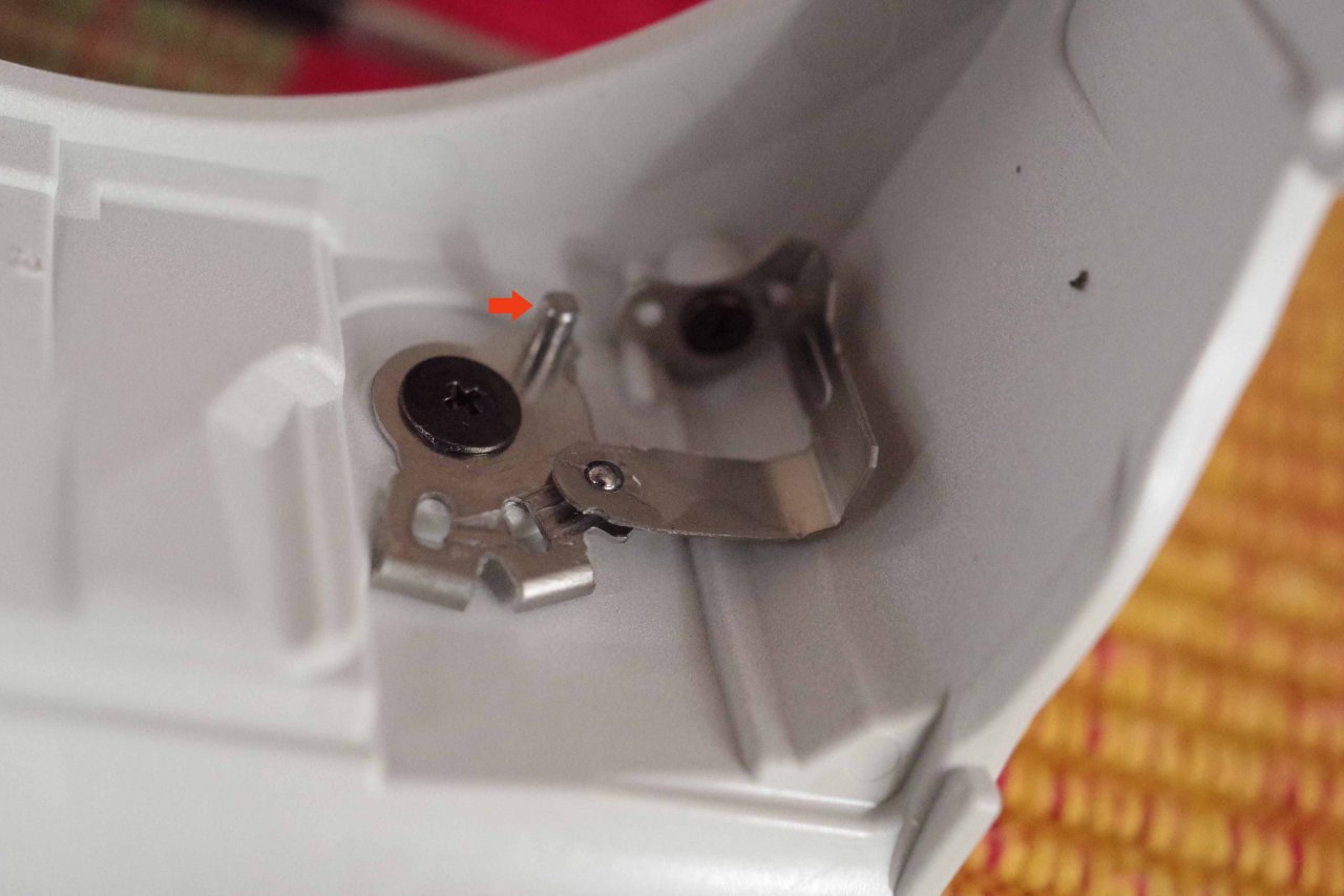
Victory! One more resurrected K30, utilising the good white solenoid from the disassembled K-r I've had in the cupboard for 4 yrs.  Took about an hour. As you say photogem, it's not that difficult. Does have a certain intimidation factor, opening up a camera, all those wires, all those parts. Plenty of scope for disaster... A few observations and pics. - I used a very small flathead screwdriver, then a slightly larger one, around the break in the casings to ease off the front. Just sufficiently in the break then twist. It's awkward to grasp if you don't do something like this.But don't carelessly push the screwdriver through and prang something... - Unscrewing (and screwing on) the solenoid is when you might zap yourself off the capacitor, as you automatically put a hand on that side to resist the pressure of your screwdriver. Screwdriver is at an angle and you need to apply good pressure. And it would be quite easy to insufficiently tighten the screw, leaving the mounting of the replacement solenoid a bit loose. - Pic 1 shows my use of a paper clip with a hooked end to hold the solenoid. - I did a practice run with a cold iron, resting the iron holding hand on a case and seeing what angle was best. I just have a simple 30W pencil iron with a new pencil tip. Unsoldering went easily. The trick to soldering is to get the wire positioned/held so that it is naturally pushing against the pin. Then when the iron is held against the pin, the solder melts and the wire end naturally merges with the blob. The pink wire first, then the purple. The ends are already tinned from being soldered. Pic 2 shows the results. - pic 3 shows the AFC-AFS-MF mechanism. The arrowed piece moves freely when the casing is detached. S is the slot the pin needs to engage in. - and don't forget the one screw underneath first before putting the base back on. And a pic from the garden with a sigma superwide II. Last edited by marcusBMG; 04-09-2020 at 12:32 PM. | |
| 04-10-2020, 01:26 PM | #14 |
 Victory! One more resurrected K30, utilising the good white solenoid from the disassembled K-r I've had in the cupboard for 4 yrs. Took about an hour. As you say photogem, it's not that difficult. Does have a certain intimidation factor, opening up a camera, all those wires, all those parts. Plenty of scope for disaster... A few observations and pics. - I used a very small flathead screwdriver, then a slightly larger one, around the break in the casings to ease off the front. Just sufficiently in the break then twist. It's awkward to grasp if you don't do something like this.But don't carelessly push the screwdriver through and prang something... - Unscrewing (and screwing on) the solenoid is when you might zap yourself off the capacitor, as you automatically put a hand on that side to resist the pressure of your screwdriver. Screwdriver is at an angle and you need to apply good pressure. And it would be quite easy to insufficiently tighten the screw, leaving the mounting of the replacement solenoid a bit loose This is why I recommend the JIS screwdrivers! They are superior to Philips or ... which would be worse, a flathead screwdriver. A JIS sits almost as well as a Torx! Not quite of course, torx is the very best. The trick to soldering is to get the wire positioned/held so that it is naturally pushing against the pin. Then when the iron is held against the pin, the solder melts and the wire end naturally merges with the blob. The soldering joints themselves look fine. One should avoid having gaps because solder itself then could break that bit easier away, it is softer. So if you all the sudden have the dark-image-syndrom again, then most likely the purple wire came off. Lets hope it won't! | |

|
« Tutorial/Repair Pentax K-70 with aperture-problem: Exchange solenoid
|
Manual: Solenoid replacement: Pentax K-S1 »
| Bookmarks |


| Tags - Make this thread easier to find by adding keywords to it! |
| body, diy, do it yourself, dslr, force, front, pentax, screws, solenoid, wires, yourself |
 Post #1 by photogem
  Similar Threads
 | ||||
| Thread | Thread Starter | Forum | Replies | Last Post |
| Manual solenoid replacement Pentax K30 / Discharge flash-condenser / Solenoid choice | photogem | Pentax K-30 & K-50 | 204 | 03-20-2024 01:14 AM |
| K-50 / K-500 Aperture Solenoid fix (DIY with pics) | madphys | Pentax K-30 & K-50 | 417 | 02-26-2024 03:09 PM |
| Genuine Aperture Solenoid Plunger Part K-30 K-50 K-S1/S2 K-500 | jhaji | Repairs and Warranty Service | 2 | 04-24-2019 03:40 PM |
| Will replacment battery charge in the GR III? | Oblidor | Ricoh GR | 3 | 04-22-2019 09:50 AM |


