Forgot Password
Pentax Camera Forums Home
 
Log in or register to remove ads.

Showing results 1 to 8 of 8 Search: Liked Posts
Forum: Maintenance and Repair Articles 03-13-2019, 10:19 AM  
Pentax Auto Takumar 35mm F2.3 Loose barrel Fix
Posted By Pedrodelta
Replies: 36
Views: 8,524
I recently acquired a lovely old 35mm f2.3 Auto Tak but was dismayed to find that the rear of the lens felt quite loose and this was most pronounced when mounted to my camera. The lens appeared to work well enough but the amount of play in the bodywork was disconcerting and I felt it needed to be addressed. I searched the internet for advice yet whilst it became apparent that others had experienced the same issue, there was no information to be found on how to address the malady.
Undaunted therefore, I determined to tackle the problem myself and in doing so, I kept a record of my endeavours, that they might prove helpful to others in a similar situation.
The process turned out to be quite straight forward and I'm delighted to claim was 100% successful. The lens is now as firm as it was when it left the factory almost sixty years ago and with care should continue to provide enjoyment for many, many years to come.

Preliminary preparations.

1/ It's not a lengthy operation but even so, make sure you allow plenty of undisturbed time to concentrate fully and uninterrupted on the task in hand.
2/ A clean, well lit and tidy work area. A white sheet, paper or linen is good to work on as small parts or screws are easily seen against a white background. I like to use a large tray to contain all the various parts.
3/ A good quality set of jewellers screwdrivers is an absolute must. Some of the screws you will be dealing with are minute and their slot heads would be easily damaged with anything other than perfectly fitting drivers.
4/ If your eyesight is challenged by small items, then a good magnifying glass or glasses will prove invaluable.
5/ A small amount of grease, lithium or silicon.
6/ Paper towels, cotton buds and some cleaning fluid.
7/ Pen, paper and or camera to make reference notes and or photo's of your progress.

Disclaimer - Proceed at Your OWN Risk

Part One
Focus the lens out to infinity, make sure the aperture is not cocked and set the aperture ring to f22
Looking at the silver metal band around the middle of the lens, the one that denotes the aperture scale and has the red dot on it, you will find three very minute screws. They may be slightly recessed and their heads hidden with dirt from years of handling. These three screws when revealed need carefully unscrewing but not removing. Sequentially unscrew each of them a couple of turns at a time until it is loose enough to slide up beneath the trailing skirt of the large focus ring. This can be acheived by using your thumb nails, pushing them into the tiny gap between the silver aperture scale ring and the black aperture adjusting ring below it and then gently and evenly applying forward pressure until it's pushed as a far up as it will go. This action will then reveal three more and larger screws on the barrel below it.

The small screws I referred to are shown by the green arrows. When sufficiently loose the sliver metal ring can be pushed/slid up in the direction of the red arrows until it's mostly hidden under the skirt of the focus ring. (See the first photo below)

Part Two

The three screws you have just revealed will probably be found to be loose. This is part of the problem but not the whole of the problem. The fact that they are loose though is at this stage an aid as they need to be removed. Again, sequentially and a bit at a time, unscrew all three, remove and put safely aside.
The lower barrel of the lens can now be seperated from the upper barrel by carefully easing them apart from each other. By firmly gripping the upper barrel with one hand and the lower barrel with your other hand to pull them apart, applying a very, very slight side to side twisting motion if necessary.
Once apart, the upper barrel can be set safely to one side as it will only be the lower barrel portion that requires more work. I'm sure at this stage too, you will be glad to learn that no helicoids are involved at any stage. (See photo's 2,3 & 4 below)

Part Three

From this remaining section the next stage is to remove the black plastic aperture adjusting ring. This is acheived by gently sliding/pulling it forwards and off. Whilst doing so, it will be prudent to keep the f22 part uppermost, as located below this point is a tiny metal barrel bearing seated in a little recess. It is this bearing that provides the click when altering the aperture. Remove this, wipe it clean and set it safely aside. The black aperture ring can also be cleaned on its inside by removing any old compacted dust and grease and again setting safely aside for the pending rebuild of the lens.
The removal of the aperture ring will have revealed yet another four screws which may be initially hidden by more old and dirty compacted dust and grease. Once this has been cleaned away, the four screws should now be prominent and will also found to be quite loose. It's the looseness of these screws which is the crux of the problem. These screws hold a two parts of the lower barrel housing together, the bottom being the metal outer barrel and the plastic being the inner barrel. These two parts need to be pushed tightly together and the four screws then firmly tightened up to re-establish the integrity of the lower part of the lens. I would suggest that they are tightened up sequentialy a bit at a time until all are firmly seated and none stand proud of the barrel. (See photo 5 below)

Part Four

The re-build can now commence and this is done in reverse order with one slight difference and that is; the black aperture ring is returned to the barrel before the little metal bearing that provides the click stops. Before replacing the aperture ring, smear a thin film of grease around the barrel where the aperture ring will sit, line up the aperture ring (there is a slot on the inside of the ring to accomodate the screw which drives the aperture blades (See photo six)) and push firmly home. Once satisfied that it is correctly seated, turn the aperture ring the full extent of its travel to the f2.3 end and then back one stop to f2.8, then looking inside the barrel underneath where the f2.8 mark is, the sharp eyed will see a small rectangular piece of spring steel secured at one end by a small screw. (See photo seven It is this spring steel plate that provides the pressure on the bearing that defines the aperture clicks and beneath it is the recess that houses the click bearing. By carefully loosening the screw, this plate can with the aid of a small screwdriver or other implement, be lifted at the opposing end sufficiantly enough to relocate the bearing. This again can be acheived by the use of a small screwdriver with a little dab of grease on the tip to pick up the bearing and then deftly manouvre it into place. Then, making sure it's covered by the piece of spring steel, re-tighten the screw and aperture clicks will have been restored. (Try not to remove the screw whilst attempting this as it's a pain to relocate it. Replacing this bearing was the single most difficult part of the whole rebuild) Now turn the aperture ring back to it's f22 position, being mindful to ensure you don't detach it once more from the barrel and the rebuild can continue. (If you like to use your lens for video work and would prefer to have a variable fluid type aperture, then this last step can be omitted)

Part Five

Continuing with the reassembly, the two parts of the lens can now be re-united. Clean as necessary, line up the bottom half of the lens with the upper part and they can be gently pushed together, a slight jiggle of the two may be required to ensure correct location of the aperture guide. Push firmly home and ensure the screw holes marry up in both barrels and the three securing screws can now be replaced. Tighten sequentialy a couple of turns at a time until all are tight, ensuring that none are standing proud of the barrel. The silver ring can now be drawn down again, ensure it lines up exactly and secured in the same manner with its three screws. Voila! You have now successfully repaired your 35mm f2.3 Auto Tak. Mount on camera, test and enjoy!!!
Forum: Maintenance and Repair Articles 03-19-2020, 03:12 PM  
Repair and Restoration Pentax 67
Posted By Aristote
Replies: 22
Views: 16,654
Hello !

Happy owner of a Pentax 67 from 1989, I wanted to perpetuate this fabulous system by buying a second case. However, to my dismay, I noticed the frightening increase in its rating, a consequence of the fashion effects and Youtube videos of Hipsters lend to all possible promotions to get views.

A solution then came to my mind, buy a defective case and refurbish it. We do it well with vintage cars, so why not with the boxes?

Current technological and production means allow us to design replacement parts at a relatively democratic cost. however, keep in mind that the more the base is damaged, the more difficult the restoration will be. For ease and saving time, we will leave on a drinking basis. I will detail the process, prices, tips and other information in order to have a complete resource that can be used by everyone. You have to keep in mind that all the will in the world does not replace the training in automobile mechanics that I acquired as a teenager. Do not venture into this kind of operation if you do not have a minimum of experience in the matter.
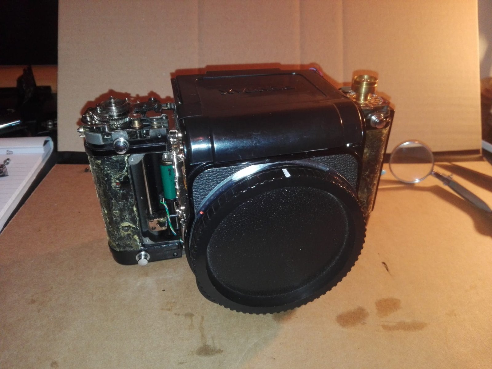
Here's the beast:

Attachment 490684
Attachment 490685
Attachment 490686

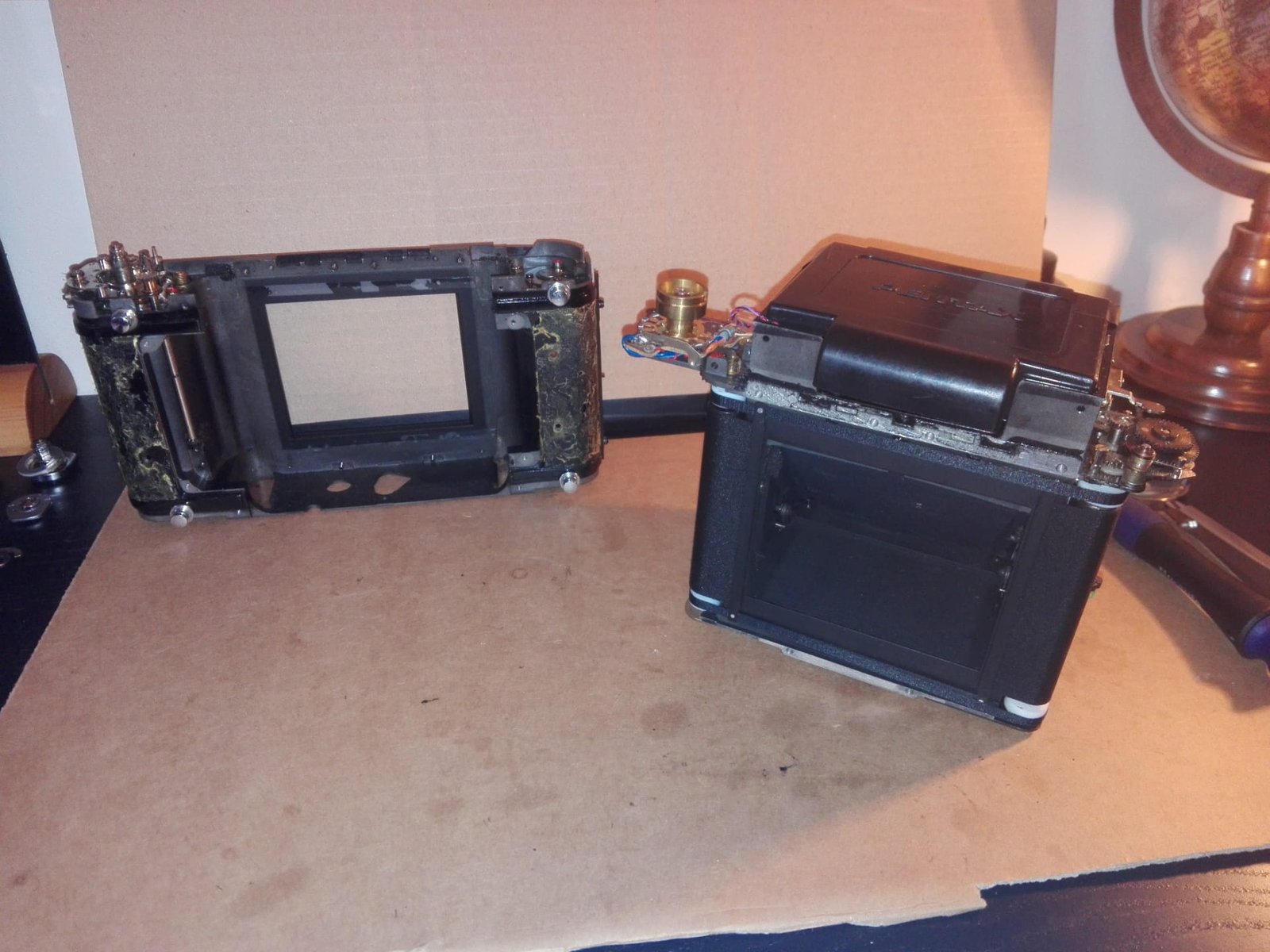
A 1989 Pentax with a decent cosmetic condition, the shutter seems to be blocked. The whole thing came back to me at 80 euros. Before starting the operation, it is preferable to draw up specifications with a specific objective to achieve. My first idea was to redo a complete painting of the chassis, it will be justified or not according to the state of the painting. The brass upper parts are not subject to corrosion, but the steel elements like the rear door yes. Therefore, it would probably be a good thing to redo a complete body. A Hammeritte type lacquer with baking seems to me a good starting choice, however I must inquire about the resistance of the product.

I based myself on the work of Oriu, an incredible French forumer who repaired his Pentax too. Without him, I would not have started this journey.

---------- Post added 03-19-20 at 03:28 PM ----------

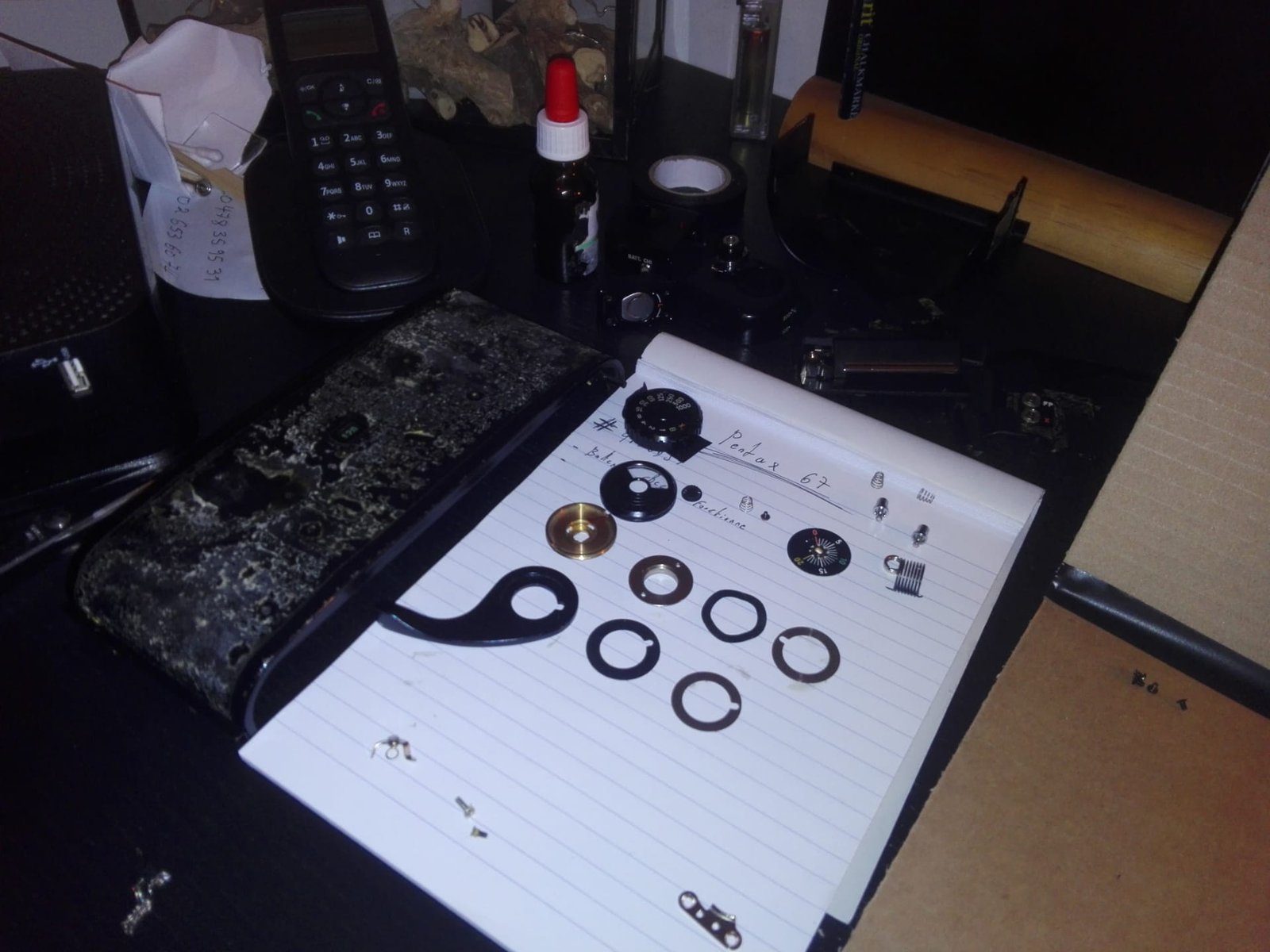
Well, I had already prepared the tools:

- Tweezers with magnifying glass for small assembly parts.
- A set of gauges to calibrate the spacings.
- A caliper for measurements to the tenth of a millimeter.
- A micrometer for measurements to the hundredth of a millimeter.
- Precision screwdrivers.
- Trichlorethylene.
- WD40 (penetrating and protective for electrical contacts).
- A syringe loaded with lithium grease.
- A syringe loaded with synthetic engine oil.
- Disposable nitrile gloves.
- Various consumables.
The service manual not to be silly and go blind:
https://www.manualslib.com/manual/99867 ... x-6x7.html

I recommend consulting the manual before each disassembly step in order to have a mental diagram and know which direction to go. I will reference the pages during the steps so that you have a precise view of the operations, these will be highlighted in red in the parentheses.

The service manual tells us that I need more specific tools (page 108), I will manufacture them according to the disassembly, because I need to visualize and measure the spacings for machining ( Caliper and hard tweezers can make the job too).

First, we will prepare the disassembly of the screws by pouring a drop of WD40 on each. To facilitate its application, we will incorporate the WD40 in a pipette bottle, the dosage will be more precise with no risk of splashing. The WD40 is a powerful penetrating oil with great infiltration power. In fact, over time, the screw threads oxidize when you never disassemble them and it becomes difficult to extract them without ruining the screw head. I recommend waiting 30 minutes for the product to take effect.

Once the time has elapsed, I begin removing the barrel of speeds, the view counter, the cocking lever, the upper covers and the ornamental plastics (these are brittle and I do not exclude 3D printing with acetone smoothing).

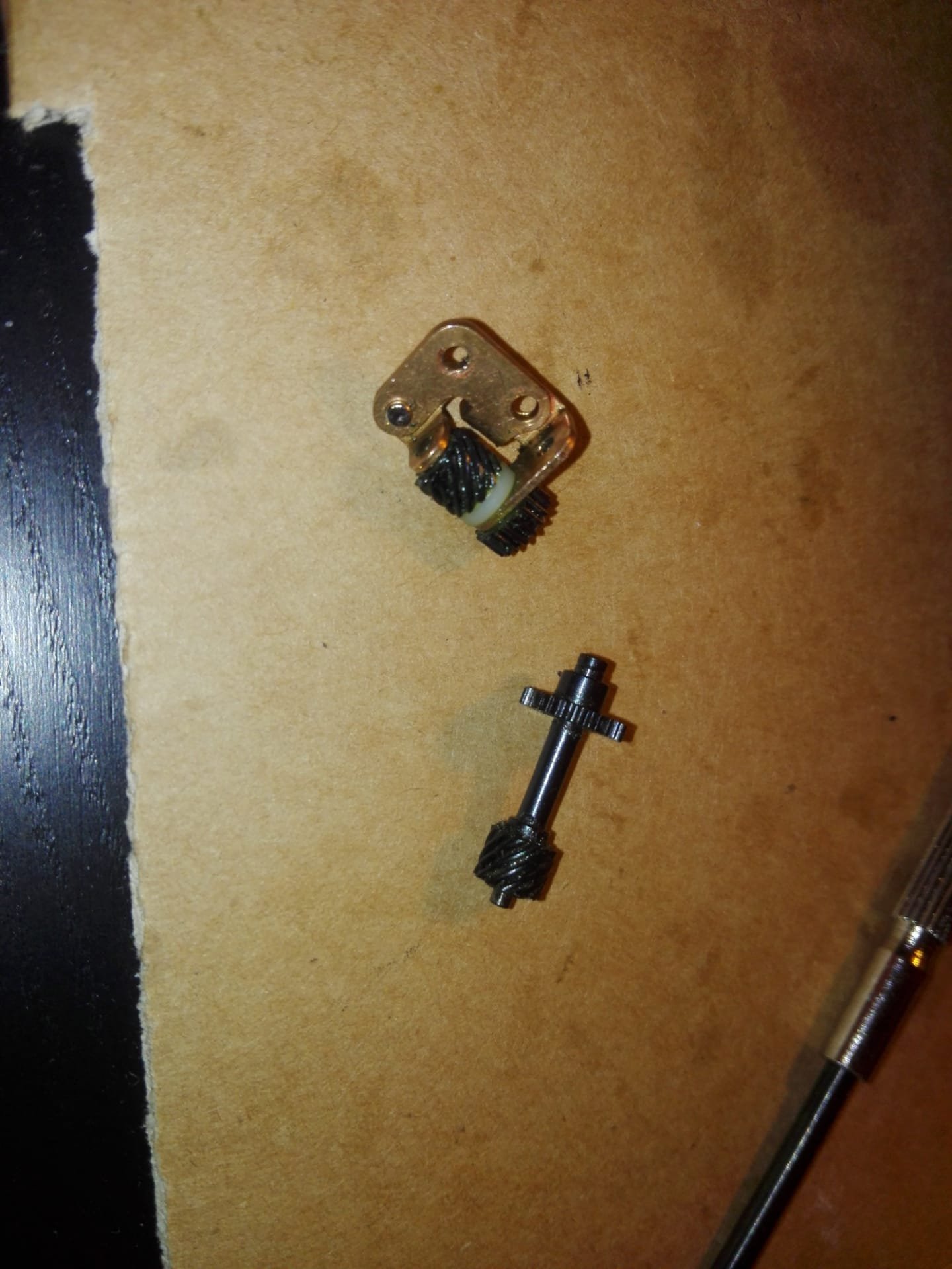
A part was broken in the mechansim. I guess that he felt, the piece had traveling in the mechanism and bending the shutter gears.


I started my journey of chassis / cage decoupling, but not obvious at all! As specified in the service manual, the coupling elements of the arming mechanism must first be removed from the cage. I started with what seemed to me the simplest, point 2 which includes the elements C8 and C9. Once the two screws removed (one long and one short), it is necessary in addition to that to extract the circlip LW24 which holds the control rod of the mechanism, otherwise the extraction is almost impossible. To do this, a flat screwdriver and patience, because it is badly placed and the place is cramped. Furthermore, once deposited, it is housed in the mechanism…


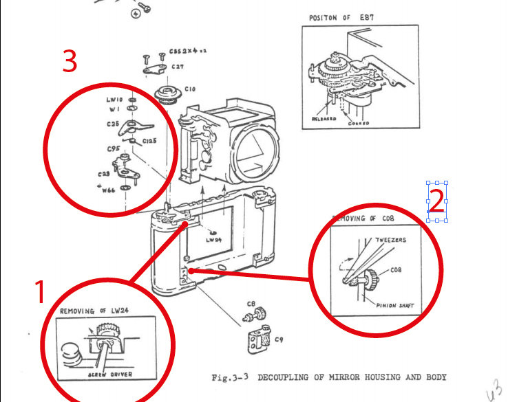
We then go to the mechanism which does not really reassure me and which I left fallow ... First C27 with its two screws. The C25 shouldn't be a problem. On the other hand, I am less sure for C23. Indeed, its retaining screw has an ugly head and requires specific tools


---------- Post added 03-19-20 at 03:31 PM ----------

We move forward !

The box is detached from the cage and I will be able to try to understand where the curtain is blocked. New on this model compared to the old one, we notice that the ribbons of the curtain are now in fabrics and no longer in plastic. One of them has slightly derailed from the roller and I wonder if the tension is correct, because it is against, but moves easily. Precision for the head of screw C23,


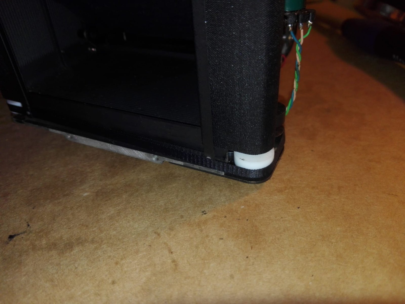
I had to remove it delicately with a pliers with fine nozzle, because, I did not succeed in machining a satisfactory tool. However, the tightening torque is not high, everything went well with a little patience and a lot of WD40 it came easily. You will still need a correct tool for reassembly. Case to follow !

---------- Post added 03-19-20 at 03:35 PM ----------

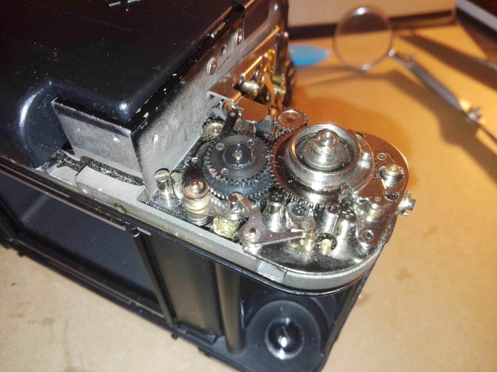
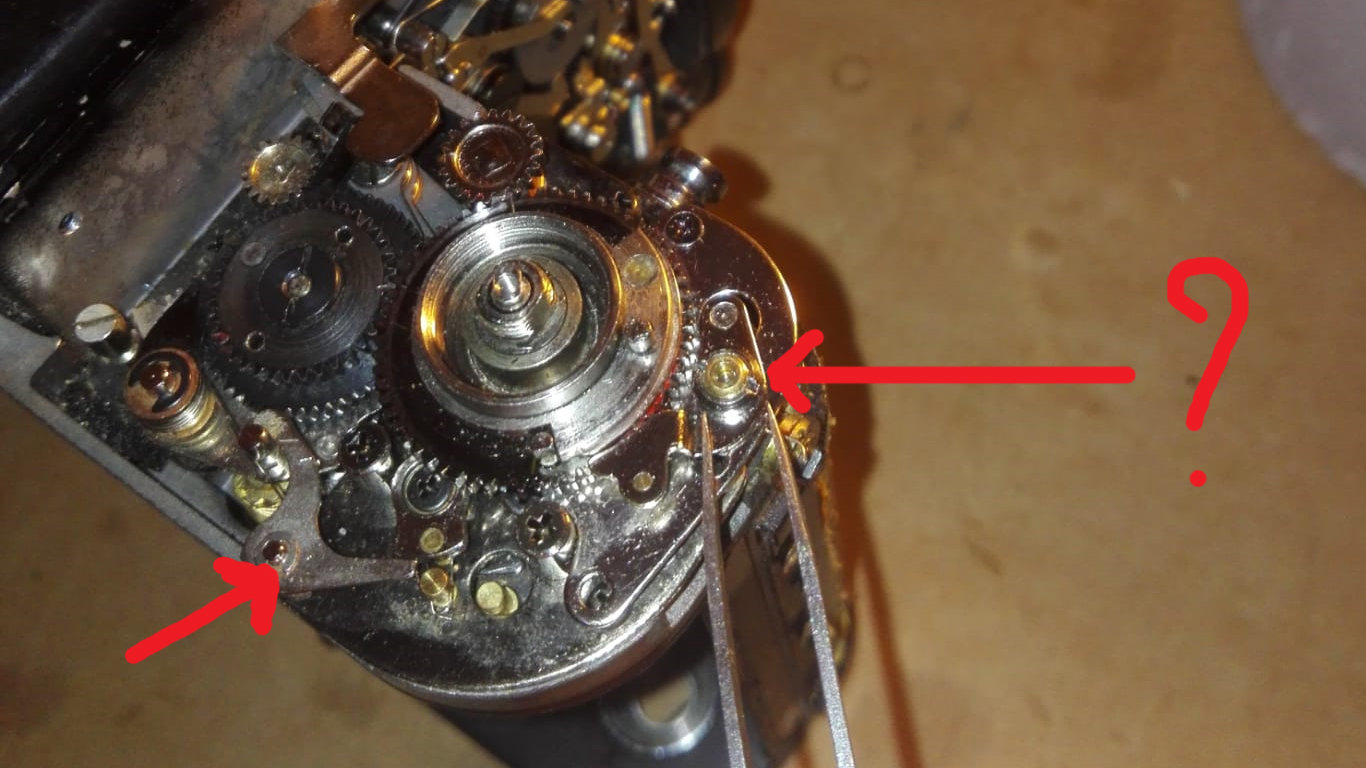
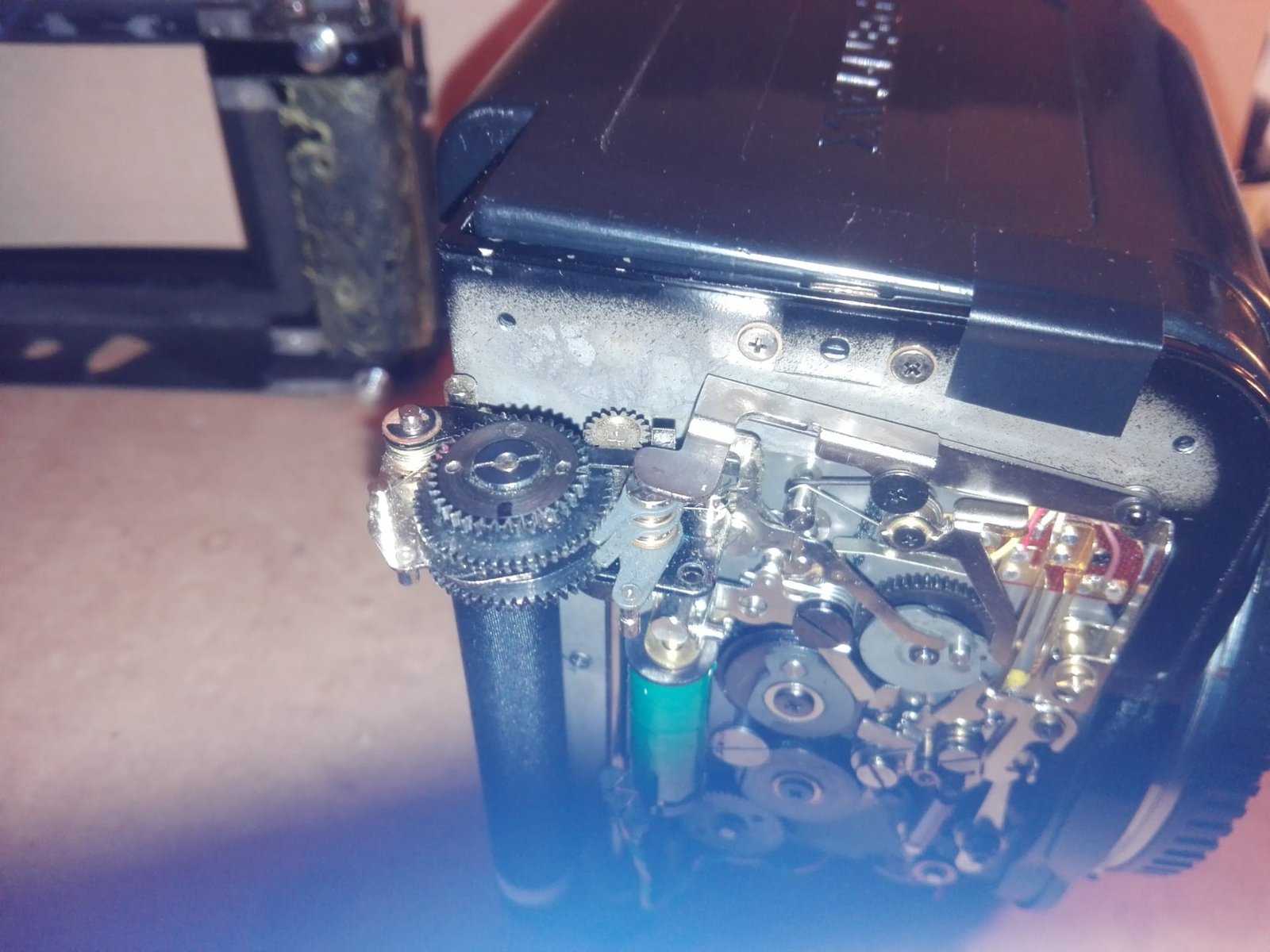
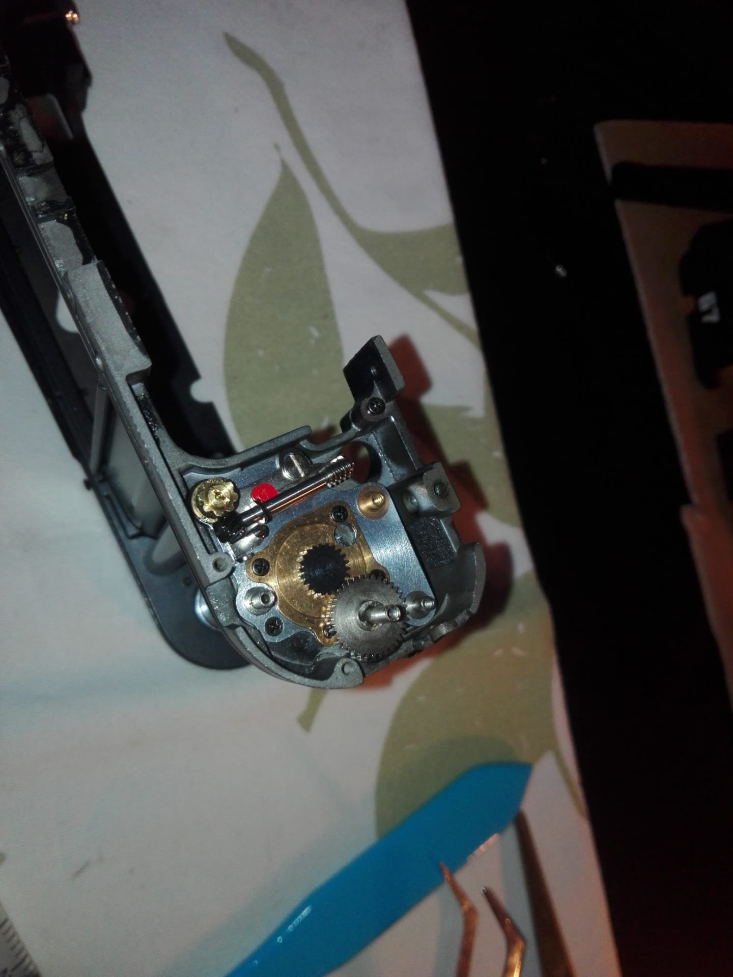
As we can see in the photo, the pinion axis has completely deflected backwards! Which explains why the cam was twisted ... The solenoid doesn't seem to release the cam either, I think at least. I have to study how it works to understand its logic ...
As with the impossible, no one is required, I will dismantle everything and straighten the axis and we will see then! I would have preferred a badly positioned but good spring…


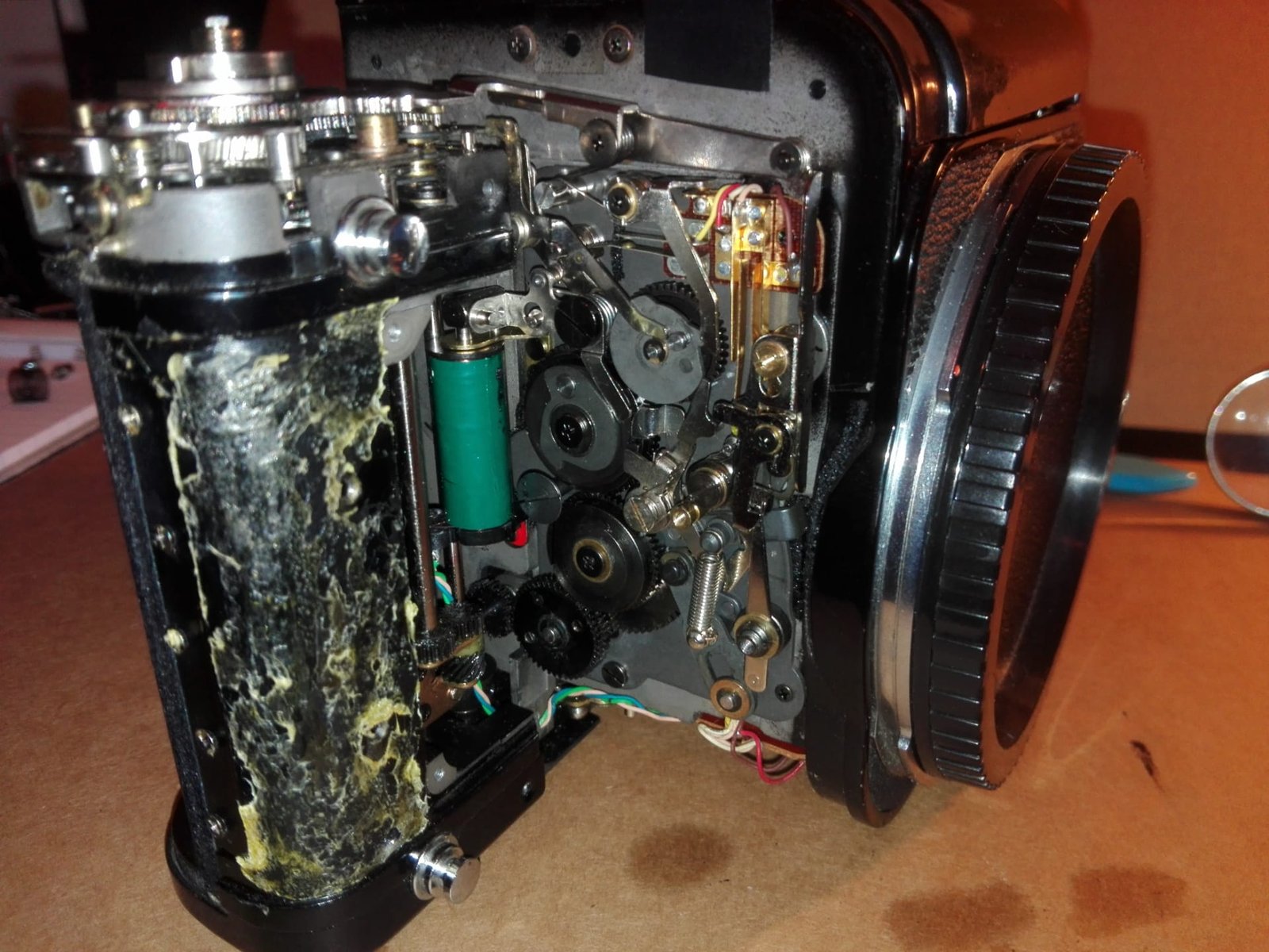
I left the cage for the end and decided to devote myself to the mechanism of the body. Indeed, it had a problem and comparing it with my functional box, I found that the winding mechanism was stopped ... No choice but to dismantle everything, we will take the opportunity to clean all the gears and lubricate all with mineral engine oil and lithium bearing grease. The latter does not disintegrate and resists high pressures, moreover it is sticky and allows the parts to be kept in their locations.

https://nsa40.casimages.com/img/2020/02/15/200215063424356470.jpg

I had a problem with the disassembly of the C73 screw which serves as an axis and support for the O-C34 plate because of a recurring problem, the inability to machine a special screwdriver. Good old method of pliers, screwdrivers and WD40 with caution, of course. Although it is still drinkable, I think I would find out to possibly redo one with a milling turner in pattern making ... To see if the game is worth the effort. Ah yes ! In my runaway, I dismantled everything without taking the time to note the locations and functions of the mechanism. So I'm going to put it all together with the exploded view and common sense. The reassembly will take time, I think ... There is a foam to replace which takes care of the maintenance of one of the springs on the chassis, it is visible on this photo.


---------- Post added 03-19-20 at 03:38 PM ----------

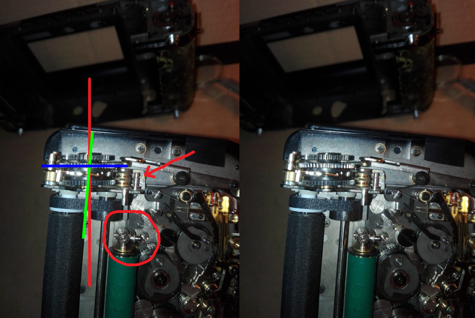
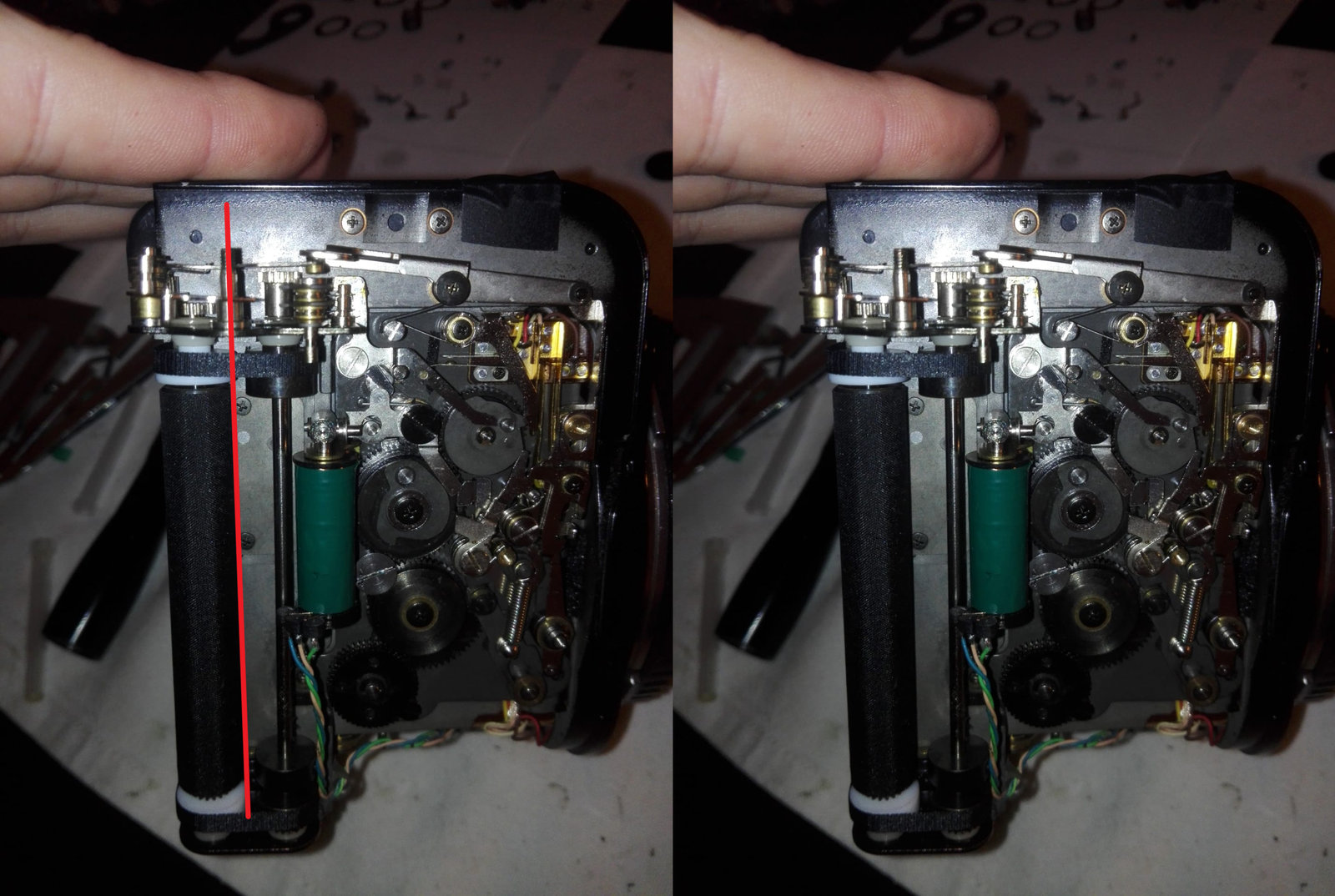
First level raised with difficulties adjusting the cams. Indeed, the springs between the supports and the cams (1 and 2) must be perfectly adjusted under penalty of having trouble tightening. To be more explicit, they do not adjust on the axis, but on the cam and loosen when moving.

You have to arm yourself with a lot of patience, skill, and a little luck to properly position the springs ... I ch ** ma ra ***! But it's done! Finally I hope it is mounted correctly, we will see when the mechanism is reassembled.

If I understood correctly, when we close the back, a protrusion pushes the cam 2 which in turn connects the worm of the view counter to the notched wheel of the upper part (0-C34). However, I can not grasp the logic of the cam 1 and the rewinder locker which is housed at point Z. I also still have a little trouble on the connection point 3, its positioning makes me perplexed …

I will also look for a method to correctly align the star wheel of the 0-C34 axis with the lower cams.


---------- Post added 03-19-20 at 03:41 PM ----------

We had seen that the pinion axis was deviated from its axis because of a possible fall or forcing of the mechanism (I don't always know not). In both cases, it was not won ...

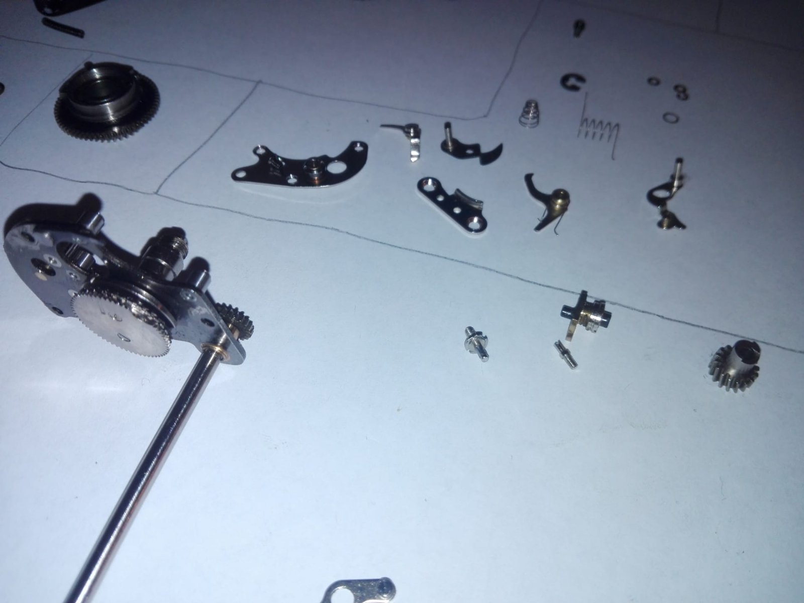
I carefully dismantle the screw that fixes the group of toothed wheels in order to extract the pinions one by one. Without adequate tools, I use the same method, screwdriver and flick counterclockwise, the tightening torques are very low and therefore the screw comes easily. And there I see that the axis is badly bent.
Luckily, brass is easy to work with and the straightening method is simple, a small pliers with insulation around the teeth so as not to damage the axis. The brass is soft and the thread fragile. We will also remember to put the screw back on the net so as not to damage it during the folding phases. We grasp the axis and we proceed by blow, millimeter so as not to risk breaking the part. We especially take our time in this kind of operation.

For the anecdote, I remember one of our school visits during my mechanical years at Herstal Group where a barrel straightener officiated, he had the particularity to do it with the naked eye without measuring instrument, it was fascinating and it inspired me to do the same with this beautiful Pentax 67!
Here is the straightened axis:


I apologize for the round trips on the different parts of the box, but I like to roam in the landscape and follow a precise frame quickly bores me ... See you soon !
Forum: Maintenance and Repair Articles 03-19-2020, 02:54 PM  
Pentax 67 - Restoration Project
Posted By Aristote
Replies: 35
Views: 28,397
I launched a restoration too, I'm gonna start a thread soon about that.
Forum: Mini-Challenges, Games, and Photo Stories 02-26-2019, 02:53 PM  
Game Single In - February 2019
Posted By W412ren
Replies: 166
Views: 8,391
I really must get over sometime. My sister lives with her family about 2 hours away from you. They are in Eich.
Forum: Maintenance and Repair Articles 12-09-2015, 08:31 AM  
Pentax-A 50mm f1.7 Aperture ring repair
Posted By MVK
Replies: 77
Views: 73,358
Thanks willdmo. I will be more careful. I also need to do similar surgery on my A 50mm 1.7
Came across two wonderful videos on you tube posting links below


You Tube


---------- Post added 12-09-15 at 08:33 AM ----------

Pentax-M 50mm F2.0 repair

Found following link on you tube. Hope it helps


You Tube


Forum: Mini-Challenges, Games, and Photo Stories 05-26-2013, 01:53 PM  
Thematic Single Challanges, Win an INDUSTAR 50-2
Posted By Jools
Replies: 10
Views: 1,686
Well to anybody who is interested, this is one great little lens.
I did the Monthly Challenge with the Industar 50-2 once. Learned a lot from it and it has become a steady in my arsenal.
Go for it folks, wildmo is offering a gem.:)
Forum: Pentax Lens Articles 08-12-2010, 04:24 AM  
Sticky: How to use/meter Manual & M42 Lenses on all Pentax DSLRs (K-1, K-3, K-5, K-30, etc)
Posted By Adam
Replies: 358
Views: 416,812
Many Pentax DSLR owners want to use M42 screwmount (Takumar) lenses, or M or K manual lenses, on their cameras because of the low cost and relatively high image quality of these lenses.


If you're wondering whether or not these lenses can be used with Pentax DSLRs (or the K-01), then the answer is yes! Pentax as well as third-party manual and screwmount lenses can easily be mounted on any Pentax DSLR (such as the K-1 series, KP, K-3 series, K-70, K-S2, K-S1, K-50, K-500, K-30, K-5 series, K-r, K-x, K-7, K10D, K100D, K200D, *ist D, etc.) Just follow this guide!


Modern Pentax DSLRs use the Pentax "K-mount", which employs a bayonet and therefore differs significantly from the M42 screw mount. The older manual M and K (SMC Pentax-M, SMC Pentax) lenses actually use the bayonet, so they will not need an adapter - you can skip straight to the lower portion of this article (starting at "Important!") for information on how to meter with those lenses. Screwmount lenses usually have "Takumar" in their names, and in order to mount screwmount lenses on your k-mount body, you'll need a Pentax k to m42 adapter. Pictured above is the genuine Pentax adapter, which is ideally the one you want to get. Similar third-party adapters are also available. Caution: Many third-party adapters, such as this one, have a protruding flange which will prevent you from focusing all the way to infinity. If you want to buy a third-party adapter (they're generally cheaper), make sure that they don't have this flange. Here's an example of a good third-party adapter.

Once you have your adapter, the next step is to install it on your camera (it can easily be put on and removed on-the-fly). Check out the m42 to k adapter manual.


After you've installed the adapter, you'll want to mount the lens. This is done by screwing it into the camera until the lens feels firmly attached. The focusing window and lens ring should line up with the camera just like any other lens. Now that your lens is mounted, let's talk about how to take photos with it.

Important! The hard part is to get the camera to actually fire when a manual lens is mounted. In order to accomplish this, enter your camera's custom function menu, select the "Using Aperture Ring" setting (usually at the end of the menu, #21 on the K-7, #27 on the K-5, #27 on the K-3, #26 on the K-1), and set it to 2 (allowed). Once you do this, the shutter will at least fire, as it wouldn't have with this setting disabled (you would simply have seen an F-- indication on the top LCD/info screen). The setting description should read: 'Shutter will release when aperture ring is not set to the "A" position' when "allowed" is selected. Also note that the mount on the lens must be conductive for electrical current so that it shorts the electrical contacts on the camera body. All Pentax manufactured lenses have a conductive mount, but some third party lenses do not in which case the area of the mount touching the contacts must be sanded down.

K-30, K-50, K-500, K-70, K-S1, K-S2 and K-01 users: make sure you also set your green button "action in M/TAv Mode" to Tv SHIFT. This is found under the button customization menu (page 3 of the main menu) on the K-01 or as a custom function on the K-30, K-50 and K-500. On the K-S2 and K-70, look under the e-dial programming sub-menu under button customization in the record menu.

Finally, ensure that auto ISO is disabled.

At startup, if your camera asks you for the focal length, enter the actual focal length as labeled on the lens. This will ensure optimal Shake Reduction performance. For zooms, you can use the lower end of the zoom range (this ensures that there will be no over-compensation), or the focal length that you shoot at most often.

Now, let's discuss metering. Since manual lenses don't feed aperture data to the camera, the only way for the camera to check how much light is being passed through the lens is to measure the light while the lens is stopped down. Follow this procedure to properly meter with a screwmount, M, or K lens:

___0. Ensure that the "Using Aperture Ring" custom function is set to "2 (allowed)" (K-30/50/500/01 users must also ensure that the green button is configured to Tv Shift in M/TAv Mode) as described above
  1. Set your camera to M mode using the mode dial (your camera won't fire in other modes*)

  2. Compose and focus your image.

  3. Using the aperture ring (the ring at the very back of your lens; it will have numbers such as 2.8, 4, 5.6, 8 written on it), select your desired aperture setting. Note that the smaller the aperture number is, the more light passes through the lens, and the blurrier the out of focus areas of your photograph will be (and vice-versa). Note your lens will not stop down until step 5.

  4. [Screwmount lenses only] Switch the diaphragm clutch on your lens to "Manual" (you can leave it on Auto when composing and focusing if you don't want a dark viewfinder).

  5. Measure the light by either pressing the "Green Button" (older bodies may use the Av button), or pushing your power button to DOF preview mode (only available on high-end bodies). Your camera will automatically set the shutter speed for you.

All that's left now is for you to press the shutter release button to take your photo. Congratulations- you've now learned how to use M42 and M & K manual lenses with Pentax DSLRs!

*Screwmount lenses may also be used in Av mode since they are always stopped down to the aperture you will be shooting at (unlike M&K lenses, which are stopped down only when the shutter is released or when you meter as described above).

Note: if your aperture ring has an "A" on it, instead of doing stop-down metering as per this guide, you'll want to set the ring to "A" and use the camera's scrollweel to adjust the aperture via Av mode.

Click here if you found this article helpful!

Video version:


You Tube


Forum: Film SLRs and Compact Film Cameras 10-20-2012, 04:47 PM  
Asahi spotmatic sp battery recommendation
Posted By rayallen
Replies: 73
Views: 150,426
Spotmatic Battery Information.
Here is the information about batteries that is sent to each new member of the Yahoo! Spotmatic Group (of which I am the owner):

Spotmatic Battery Information

The most experienced members of the Spotmatic group have compiled the information below and many of them have been using Spotmatics since they purchased them brand new in the sixties and seventies. This information is being provided so that you do not have to ask about it as a discussion topic on the forum. It has already been discussed and answered many times and there is nothing more to add so please do not ask again. All you need to know is contained in this document.

For battery cap information go to the bottom of this document.

In relation to batteries, there are 5 groups of Spotmatic cameras:
1. SP Series. This includes SP, SP500, SP1000, SPII and SPIIA.
2. SP F
3. Electro Spotmatic and ES
4. ESII.
5. SL. This camera has no meter and, thus, no battery.

SP Series
The 1.35-volt mercury (mercuric oxide) battery originally used in the Spotmatic SP is no longer available due to environmental protection laws.
Replacement batteries available today are 1.55-volt but the Spotmatic uses a "bridge" circuit in its meter, making it insensitive to battery voltage variations. So, despite what you may have read - No meter recalibration is necessary as all Spotmatic SP series cameras can handle the increased voltage.

The alternatives are:
• Spend about $30 for an adapter from CRIS Camera Services (Camera Repair by CRIS Camera Services: Digital Camera Repair: Canon, Fuji, Nikon, Pentax, Ricoh, Sigma) and a battery to insert into it. But this would be a waste of money as it is definitely not required.
• Spend about $10 for a Wein Products MRB400 cell (modified Zinc-Air cell). They are quite expensive and have a limited life (about 6 to 12 months) unless you remove the battery after each use and seal up its air hole (it needs air to work). This is not a recommended solution.
• Spend about $3.00 for one of the many 1.55-volt silver oxide batteries available over the Internet, at Radio Shack, most drugstores, camera stores and even some supermarkets. They will last you for about three years if our experience is typical. Make sure you insert it the right way for proper polarity, and take up the excess space in the battery box with a rubber O-ring from the hardware store, that will cost you about 49 cents. You might have to bend up the battery contact in the battery box to make good contact.
• Silver oxide batteries that work are: Mallory PX-400 or RM-400-R, Varta V394, Maxell SR936W or SR936SW, Renata 394, or any type 392 equivalent.
• Do not be tempted to use alkaline battery equivalents as they have a much steeper discharge curve. The silver oxide batteries have a flat discharge curve similar to the old mercury batteries.


SP F.
• Mallory PX625, Duracell PX625A, Excel Z625PX, Eveready E-625N.
• The Spotmatic F uses a dual coil meter movement that, like the bridge circuit, cancels out battery voltage variations on the level we are dealing with here. So it is immune to the difference between 1.35v and 1.5v, too. The original battery for the Spot F was a mercury type. In this case, Pentax used the identical circuit in the KM and K1000, without any electronic changes. They substituted the silver types with NO ALTERATION at all.

Electro Spotmatic and ES.
6-volt Eveready #544, Duracell 28L Lithium.


ESII.
Eveready S76E, Mallory MS-76H, in fact any 76-type battery works -A76, S76, MS76.

Places on the Internet to purchase from:

photobattery.com - photo battery Resources and Information. This website is for sale!
Batteries Plus battery store - All your battery needs for Laptop, camera, cell phone, camcorder, SLA, batteries recycling and much more (good model search facility)
Swatch Battery.com Swatch batteries, watch batteries Watch Battery Renata Energizer (very cheap, good quality)
Welcome to MDBattery.com - Right Battery | Right Price | Right Now ? (you need to know the battery number you want)
Welcome to MDBattery.com - Right Battery | Right Price | Right Now ? Look for the S400PX (for SP series) or the S625PX (for SPF) on this page.

Battery Caps.
The following are two known sources for Spotmatic SP series and SPF battery caps:

http://gallery.bcentral.com/GID20255...ttery-Cap.aspx

Pentax Camera Service (Eric Hendrickson)
“I still have new caps for the Spotmatic.
If you would like one just send 15.00 plus 2.00 postage.
Email me at pentaxrepairs@aol.com
Search took 0.00 seconds | Showing results 1 to 8 of 8

 
Forum Jump


All times are GMT -7. The time now is 04:27 AM. | See also: NikonForums.com, CanonForums.com part of our network of photo forums!
  • Red (Default)
  • Green
  • Gray
  • Dark
  • Dark Yellow
  • Dark Blue
  • Old Red
  • Old Green
  • Old Gray
  • Dial-Up Style
Hello! It's great to see you back on the forum! Have you considered joining the community?
register
Creating a FREE ACCOUNT takes under a minute, removes ads, and lets you post! [Dismiss]
Top